
Integrated Alarm/Remote Start System Installation/Operating Manual


WIRING
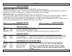
J-3 2 PIN PLUG (WHITE)
RED-BLACK WIRE: PIN 1: DOME LIGHT ILLUMINATION (-) (REQUIRES RELAY)
Connect to terminal 85 of relay. This wire turns the dome light on for 30 seconds upon disarming of the alarm. If
the ignition is turned on or the alarm is re-armed, the dome light will turn off again.
WHITE-YELLOW: PIN 2: HORN HONK OUTPUT (-) (MAY REQUIRE RELAY)
This wire provides a pulsed 150mA negative output for honking the vehicle's horn when the alarm is triggered.
Connect this wire to the horn relay in the steering column. If there is no horn relay you must install one.
NOTE: Some vehicle horns operate only with ignition on. This will require rewiring the horn circuit in order for the
alarm system to operate the horns. Call technical support for details.
J-4 2 PIN PLUG (BLUE) J-5 2 PIN PLUG (RED)
PROGRAM/OVERRIDE BUTTON LED INDICATOR (Red flashing light)
J-6 3 PIN PLUG (RED)
GRN/BLK PIN 1: NEGATIVE REMOTE OUTPUT (Optional)
RED PIN 2: FACTORY DISARM (Negative pulse)
YELLOW PIN 3: VACUUM INPUT (Used when installing a vacuum switch for engine monitor)
J-7 3 PIN PLUG (WHITE)
GREEN PIN 1: NEGATIVE LOCK Connect directly to negative lock/unlock systems. If vehicle uses
RED PIN 2: +12V For Relays positive door lock signals or reversing polarity type, then external
BLUE PIN 3: NEGATIVE UNLOCK relays must be added. Door lock wires are usually found in
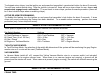
J-8 4 PIN SENSOR PLUG (22 GAUGE WIRES)
WHITE PIN 1: NEG. PRE-WARN The Dual Stage Pre-Warn Shock sensor connects directly to
BLACK PIN 2: SENSOR GROUND Alarm Brain with 4-Pin harness. Note: If adding additional
BLUE PIN 3: NEG. TRIGGER sensors, you must diode-isolate the extra sensor’s trigger
RED PIN 4: SENSOR +12V wire. Place a diode in-line with band (cathode) towards the
sensor.
OPERATION
5