PART LIST (Ships Separately) Top Panel Left Panel Right Panel Back Top Panel Front Top Rail 1PC 1PC 1PC 1PC 1PC Back Top Rail Front Middle Rail | Back Bottom Rail Bottom Panel Left Partition Panel 1PC 1PC 1PC 1PC M N Oo Right Partition Top Vertical Back Partition Back Panel Adjustable Shelf Panel Panel Panel 1PC 1PC PCs PCs PCS Middle Adjustable Drawer Front Drawer Left Panel |Drawer Right Panel| Drawer Back Panel Shelf Panel 1PC PCS 2 PCS PCS PCS Drawer Bottom Left Door Panel | Right Door Panel Towel! Bar
HARDWARE LIST ADDITIONAL TOOLS (Not Provided) Note: It is not recommended to use power tools during assembly. ZF oni Head Screwdriver Note: Wood dowels are intended for alignment. Additional clearance between wood dowel and per-drilled hole is intentional for ease of assembly.
Step 1. Insert cam bolts (part #2) into top panel (part A), left panel (part B), right panel (part C), towel bar left panel (part X) and towel bar right panel (part Y) using fillips head screwdriver. NOTE: Do not over tighten cam bolts. Stop tightening once threads on cam bolt are no longer visible. Step 2. Attach knobs (part #8) to drawer front panels (part Q), left door panels (part V) and right door panels (part W) using round head bolts (part #9) and fillips head screwdriver.
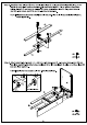
Step 3. Attach front top rail {part E) to top vertical panel {part L) using wood dowel (part #3), long screw {part #15) and fillips head screwdriver. With front top rail (part E) flat on ground, attach front middle rail (part G) and back top rail {part F) to top vertical panel (part L) using wood dowels (part #3), long screws (part #15) and fillips head screwdriver. NOTE: Please ensure screws are aligned with the per-drilled holes in top vertical panel {part L) before tightening. wa [x3 #15] x3 Step 4.
Step 5. Attach back partition panels (part M) to back top panel (part D) using wood dowels (part #3). Slide back panels (part N} into grooves of right panel (part C), back top panel (part D) and back partition panels (part Step 6. Attach back bottom rail {part H) to back partition panels (part M), back panels (part N) and right panel {part C) using wood dowels (part #3) and cam lock (part #1). NOTE: Cam locks must rotate a full 180°. See pictured insert.
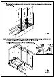
Step 7. Attach left panel (part B) to assembled unit (parts using wood dowels (part #3) and cam locks (part #1). NOTE: Cam locks must rotate a full 180°. See pictured insert. 8x6 #3 x5 Step 8. Attach double magnet (part #11) and magnets (part #12) to front middle rail (part G) using round head screws (part #13) and fillips head screwdriver. Attach left partition panel {part J) and right partition panel (part K) to back top rail (part F) and front middle rail (part G) using wood dowels (part #3).
Step 9. Attach bottom panel (part |) to assembled unit (parts using wood dowels (part #3), long bolts {part #4}, barrel nuts (part #6) and Allen wrench (part #14). #3 1 x10 #4 7x8 #6 © x8 #145 x1 Step 10. CASTER INSTALLATION Attach locking casters (part ZE) and casters (part ZF) to bottom panel (part I} using large round head screws (part #10) and fillips head screwdriver. NOTE: LEG INSTALLATION Do not install casters. Attach legs using instruction manual and hardware included inside leg packaging.
Step 11. Insert towel bar (part ZB) and support bars (part Z) into towel bar left panel (part X). Attach support panel (part ZA) to towel bar left panel (part X) using wood dowels (part #3) and cam lock {part #1). Attach towel bar right panel (part Y) to assembled unit (parts using wood dowels (part #3) and cam lock (part #1). NOTE: Cam locks must rotate a full 180°. See pictured insert. Step 12. Carefully tum unit upright.
Step 13. Attach top panel (part A) to assembled unit (parts using wood dowels (part #3) and cam locks (part #1). U A 2 tum clockwise to fasten NOTE: Cam locks must rotate a full 180°. See pictured insert. # 8x5 Hex (per-installed in door} in the per-drilled hole of bottom panel (part I). Then depress the top spring-loaded pin hinge so it can be placed in the per-drilled hole of front middle rail (part G). Place shelf holders (part #7) into desired position.