Fire Table CO9014
TABLE OF CONTENTS • Warnings and Cautions ....................................................................................................3-5 • Parts List ..........................................................................................................................6-7 • Assembly ........................................................................................................................8-12 • Operation ...............................................................................
Safety Information Read the instruction before use. This appliance must be installed in accordance with such regulations as are enforced. CAUTION WARNING: For Outdoor Use Only! Installer: Leave this manual with the appliance. Consumer: Retain this manual for future reference. DANGER: FIRE OR EXPLOSION HAZARD If you smell gas: • Shut off gas to the appliance. • Extinguish any open flame. • If odor continues, leave the area immediately.
You must provide propane gas and propane cylinder. Use a standard 20 lb. propane cylinder only. Use this heater only with a propane vapor withdrawal supply system. See Chapter 5 of the Standard for Storage and Handling of Liquefied Petroleum Gas, ANS/NFPA 58. Your local library or fire department should have this book. The pressure regulator and hose assembly supplied with the appliance must be used.
WARNINGS PLEASE READ THE FOLLOWING SAFETY RULES WARNING: Any guard or other protective device removed for servicing the appliance must be replaced prior to operating the appliance. The appliance is not for use with solid fuel. The installation must conform with local codes or, in the absence of local codes, with the National Fuel Gas Code, ANSI Z223. 1/ NFPA 54, NFPA58 Natural Gas and Propane Installation Code, CSA B149.1, or Propane Storage and Handling CODE, B149.2.
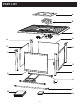
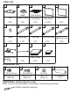
PART LIST A B C D H D G I D J E F K L M N 6
PART LIST A B C D E (8kgs) (With Burner) Lid Flame Glass Top Panel Side Panel Door Panel 1 PC 1 PC 1 PC 3 PCS 1 PC I H G F Knob Right Leg Left Leg 1 PC 1 PC 1 PC Propane Tank Support 1 PC Left Door Leg Right Door Leg N M L K J 1 PC 1 PC Cross Bar Table Cover Cylinder Cover 1 PC 1 PC 1 PC HARDWARE LIST #1 M 6 x10 mm Short Bolt 22 PCS (Extra 2) #4 #3 #2 M 6 x20 mm Bolt 2 PCS (Extra 1) M 6 Nut Nut 1PC (Extra 1) AAA Battery 1 PC ADDITIONAL TOOLS (Not Provide) Note
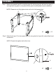
ASSEMBLY Step 1. Attach side panels (part D) to right leg (part G), left leg (part H), left door leg (part I) and right door leg (part J) using short bolts (part #1) and phillips head screwdriver. NOTE: Please do not fully tighten bolts until unit is fully assembled. G H J I D #1 D D #1 x 12 Step 2. Attach knob (part F) to door panel (part E) using short bolt (part #1) and phillips head screwdriver. NOTE: Please fully tighten bolt at this time.
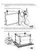
Step 3. Line up pin hinge from door panel (part E) with the holes in left door leg (part I). Attach door panel (E) to left door leg (part I) using bolt (part #2) and phillips head screwdriver. NOTE: Please fully tighten bolt at this time. G H #2 J I E #2 x1 Step 4. Lay top panel (part C) upside down on a soft flat surface. Attach assembled unit to top panel (part C) using short bolts (part #1) and phillips head screwdriver. NOTE: Please do not fully tighten bolts until unit is fully assembled.
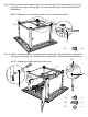
Step 5. Attach propane tank support (part K) to right leg (part G), left leg (part H), left door leg (part I) and right door leg (part J) using short bolts (part #1) and phillips head screwdriver. NOTE: Please do not fully tighten bolts until unit is fully assembled. H G K J I #1 x4 #1 Step 6. Attach cross bar (part L) to propane tank support (part K) and right door leg (part J) using short bolt (part #1), bolt (part #2), nut (part #3) and phillips head screwdriver.
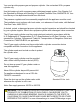
Step 7. Carefully turn unit upright. Put cylinder cover (part N) on the cylinder. Put the cylinder into the propane tank support (part K). Secure the cylinder by tightening the screw in the propane tank support (part K). Connect the hose of regulator to the cylinder. NOTE: The propane cylinder is sold separately. Use a standard 20lb. propane cylinder only. N K Step 8. Open the igniter and place AAA battery (part #4) into the igniter and tighten clockwise. Now the unit is ready to use.
Step 9. Put the flame glass (part B) into the fire bowl. Ensure flame glass (part B) is not covering pilot housing, as shown below. Place lid (part A) over fire bowl. The lid (part A) must be removed when burner is in use. Wait until the unit cools before placing lid (part A) over fire bowl. When the unit has cooled down COMPLETELY and NOT in use, put table cover (part M) on the unit. NOTE: Do not dump flame glass (part B) out of package.
OPERATION WARNING: Never use this appliance for other than the intended use. Do not use this appliance to prepare food. Initial Lighting: When lit for the first time, the appliance emits a slight odor. This is normal temporary condition caused by the “burn –in” of internal paints and lubricants used in the manufacturing process and does not occur again. Simply run the main burner on high for approximately one-half hour.
LEAK TESTING OPERATION WARNING: A leak test must be performed annually or if a part of the gas system is replaced. WARNING: Never use an open flame to check for gas leaks. Be certain no sparks or open flames are in the area while you check for leaks. Sparks or open flames will result in a fire or explosion, damage to property, serious bodily injury, or death. LEAK TESTING: This must be done before initial use, annually, and whenever any gas components are replaced or serviced.
Lighting Instructions 1. Press and hold electronic igniter button. 2. Turn the burner control to the low position, press and hold. When the burner lights, release the electronic igniter button. 3. Continue to depress the burner control knob for 30 seonds and then release. If the flame goes out, repeat the procedue. 4. Adjust the flame to the desired height with the burner control knob. Visually check the burner flames as pictured below.
MAINTENANCE AND STORAGE MAINTENANCE: To enjoy years of outstanding performance from your appliance, make sure you perform the following maintenance activities on a regular basis: • At least once a year, the unit should be inspected for the presence of spiders, spider webs or other insects. • Air flow must be unobstructed. Keep controls, burner, and circulating air passageways clean. Signs of possible blockage include: Gas odor with extreme yellow tipping of flame.
STORAGE: Between uses • Turn the control knob to “OFF” position. • Disconnect LP source. • Store appliance upright in an area sheltered from direct contact with inclement weather (such as rain, sleet, hail, snow, dust and debris). • Cover appliance to protect exterior surfaces and to help prevent build up in air passages. NOTE: Wait until appliance is cool before covering. During periods of extended inactivity or when transporting • Turn the control knob to “OFF” position.
TROUBLESHOOTING PROBLEM PROBABLE CAUSE SOLUTION Low heat / Low flame when valve turned to high. For propane- improper lighting procedure. Ensure lighting procedure is followed carefully. The valve must be in the off position when the tank valve is turned on. Turn tank on slowly to allow pressure to equalize. See lighting instruction. Pipe must be sized according to installation code. Burners burn with yellow flame, accompanied by the smell of gas. Possible spider web or other debris.