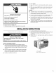
AIR CONDITIONER For questions about features, operation/performance, accessories or service call: 1-800-253-1301 par[s, Table of Contents ................................................
TABLEOF CONTENTS AIR CONDITIONER SAFETY ......................................................... INSTALLATION REQUIREMENTS ................................................ Tools and Parts ............................................................................ 2 3 3 Location Requirements ................................................................ 3 Electrical Requirements ............................................................... 4 INSTALLATION INSTRUCTIONS .................................
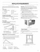
INSTALLATIONREQUIREMENTS Gather the required tools and parts before starting installation. Read and follow the instructions provided with any tools listed here. Tools needed IMPORTANT: Observe all governing codes and ordinances. Check the location where the air conditioner will be installed. Proper installation is your responsibility. Make sure you have everything necessary for correct installation.
Through-the-Wall Specific electrical requirements are listed in the chart below. Follow the requirements for the type of plug on the power supply cord. Installation The wall opening measurements should be: Power supply cord Wiring requirements • Height: 18" (45.7 cm) plus twice the thickness of wood used to build frame. • • Width: 26" (66 cm) plus twice the thickness of wood used to build frame. 115 volt (103.5 min. 126.5 max.) • 0-12 amps • Depth: 2" (5 cm) minimum to 8" (20.3 cm) maximum.
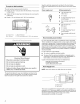
2. Press RESET. 3. Press TEST (listen for click; Reset button will trip and pop out). 4. Press and release RESET (listen for click; Reset button will latch and remain in). The power supply cord is ready for operation. NOTES: ElectricaJ ShockHazard Plug into a grounded Do not remove 3 prong ground • The Reset button must be pushed in for proper operation. • The power supply cord must be replaced if it fails to trip when the test button is pressed or fails to reset.
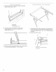
Using the tray back as a template, against outside edge of stool. center in windowsill C A. Tray back B. Windowsill C. Outside edge of stool 2. Using the 2 inside screw holes in tray back, mark screw locations on windowsill for mounting the SMART-MOUNT tray. 1. To assemble the tray frame, insert tab on tray back into slot on tray side. Check to see that the tab is engaged and the 2 pieces are aligned. Insert 2 - #8 - 18 x 1/4"hex-head screws to secure. 2. Repeat with other tray side. TM C A 3.
Attach 1. 3. Place one end of tray center over carriage bolt. 4. Then place flat washer, lock washer and hex nut. support legs Determine the correct slots on the tray side from the type of exterior construction of the building. Thin wall construction (vinyl, wood, etc.) A A. First and second slots Thick wall construction NOTE: Do not tighten. The leg must be able to move freely to adjust angle when installed. (brick} A ........... A ....... i%11 ........ A.
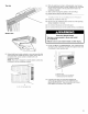
Install SMART-MOUNT 1. 2. '_Tray Assembly in window From inside, place SMART-MOUNT tray, support legs facing down, in the window. Match the holes in tray side with the predrilled holes in windowsill. TM Using 2 - #10 - 12 x 11/2"slot-head wood screws, secure the tray frame to the window. A. #10 - 12 x 1 _" slot-head Install side curtains NOTE: Attach curtains to unit before placing unit in window. 1. Insert curtain into curtain frame. Make sure curtain end locks into curtain frame.
Top view 6. While the right-hand curtain is still extended, insert screws into top and bottom slots of curtain. Using #8 x %" pan-head screws, screw curtain to the top and bottom holes in air conditioner cabinet. 7. Slide curtain housing into guides as far as it will go. 8. Repeat above steps for left-hand curtain. • Handle air conditioner • Be sure your air conditioner does not fall out of the opening during installation or removal. • Do not block the louvers on the front panel.
Correct installation Attach side curtains to window m 1. Pull left-hand curtain frame out until it fits into the window channel. Repeat with right-hand curtain frame. 2. Insert one of the #8 x %" round-head screws through lefthand curtain frame and into the window channel to fasten the curtain frame to the window. 3. Repeat for right-hand curtain frame. B m _ i ¸'_¸_'¸¸¸¸ Front view C A. Window sash B. Top channel C.
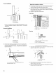
4. Attach window-lock bracket to window sash with #8 x 3/4" round-head screw to secure window in place. Option 2--Plaster wall with no molding If the plastered wall is to be flush with the cabinet and no molding is used, the wood frame must be set 1/2"(13 mm) into the inside wall. A ......................... [H AB C B A. Upper window sash B. Window-lock bracket A. Plastered wall B. Inside wall C. Wood frame D.
7. Place a 3/4"(2 cm) thick by 2" (5 cm) wide wood strip on the bottom of the opening against the inside edge. A. 17¼" (43.8 cm) B. 2" (5 cm) wide 8, C. ¾" (2 cm) thick D. Indoor side of wail opening Center the tray back in the opening and align it with the inside edge of the opening. Using the 2 inside screw holes in the tray back, mark screw locations for mounting the SMART-MOUNT tray. TM 1. To assemble the tray frame, insert tab on tray back into slot on tray side.
Attach 1. 3. Place one end of tray center over carriage bolt, 4. Then place flat washer, lock washer and hex nut, support legs Determine the correct slots on the tray side from the type of exterior construction of the building. Thin wall construction (vinyl, wood, etc.) A A. First and second slots Thick wall construction NOTE: Do not tighten. The leg must be able to move freely to adjust angle when installed. (brick) A ...... iiiiiiiiii ...... A. Hex nut B. Lock washer C. Flat washer A.
Right Side Install SMART-MOUNT 1. '_Tray Assembly -_2 in Wall Opening From inside, place SMART-MOUNTTMtray, support legs facing down, in the wall opening. Match the holes in tray side with the predrilled holes in wall opening. A. #10 - !2 x ! _" slot-head wood screw NOTE: If the exterior of building can be damaged by support legs, place a board between the wall and support legs. 3. 2. With tray center pushed away from the wall opening, place a level on the angled edge of tray side.
2. ii;:;_O_ii!!;;;ii_iiO, iii'_i_ii_i4!i:i? ,_!i!_,,ii_ ¸_iiiiiiiii'Ol%il;;!ii!_iO_'i_i!?_il ¸¸_¸ _!_!l%_,OL_ii:!!iii_iii'_i_i_ i!i%!i:i_ W:C_l!i If the feet on the bottom of the air conditioner do not rest on the wood strip, remove the air conditioner and adjust the SMART-MOUNT tray until feet rest on the wood strip. TM • Handle air conditioner with care. • Be sure your air conditioner does not fall out of the opening during installation or removal. • Do not block the louvers on the front panel.
4. NOTE: Allow for removal of the air conditioner at a later time for routine annual maintenance. If the bottom of the air conditioner does not sit against the bottom of the SMART-MOUNT tray, remove air conditioner and adjust angle of tray until air conditioner sits against the bottom of the tray. TM 0 EJectrical Plug into a grounded Do not remove Shock 3 prong ground Hazard outlet. prong. Do not use an adapter. A. Air conditioner sitting on SMART-MOUNT" B.
Mode Temperature 1, Press MODE until you see the indicator light come on for the setting you desire. 2. Choose Auto, Cool, Fan Only or Power Saver. • • Auto--Cools room while it automatically controls fan speed. You cannot change fan speed, but you can adjust temperature by pressing the plus or minus button. • Cool--Cools room. You can adjust temperature by pressing the plus or minus button. You can select fan speed by pressing FAN SPEED. • Fan Only--Only the fan runs.
To set the Timer to turn on the air conditioner, previous settings: 1. Turn off air conditioner. 2. keeping To operate Press TIMER. Timer indicator light will flash. Hour indicator light will turn on, and display will show remaining hours before air conditioner will turn on. 3. Press the plus or minus button to change delay time (1 to 24 hours). 4. Press TIMER again or wait 10 seconds. Timer indicator light will remain on. Hour indicator light will turn off, and Room indicator light will turn on.
Toselectthefanspeed(inCool,FanOnlyor PowerSaver modeonly): 4, Press TURBO, HIGH or LOW. Press TIMER again or wait 10 seconds. Timer indicator light on air conditioner will remain on. Hour indicator light on air conditioner will turn off, and Room indicator light on air conditioner will turn on. Display on air conditioner will show the current room temperature. To set Timer to turn on air conditioner, changing the previous settings: 1. Turn on air conditioner. 2.
Exhaust Control Temperature (on some models) Push the Exhaust control CLOSED for maximum continuous cooling, Pull the Exhaust control OPEN to allow you to draw stale or smoky air from the room, • Open--pull • Closed--push to exhaust room air to the outside to circulate room air Turn the TEMPERATURE control to a mid-setting. Adjust the air conditioner's performance by turning the Temperature control clockwise for maximum cooling. For less cooling, turn the TEMPERATURE control counterclockwise.
AIR CONDITIONER CARE Your new air conditioner is designed to give you many years of dependable service. This section tells you how to clean and care for your air conditioner properly. Call your local authorized dealer for an annual checkup. Remember... the cost of this service call is your responsibility. 3. Use a vacuum cleaner to clean air filter. If air filter is very dirty, wash it in warm water with a mild detergent. Do not wash air filter in the dishwasher or use any chemical cleaners.
TROUBLESHOOTING You can solve many common air conditioner problems easily, saving you the cost of a service call. Try the suggestions below to see whether you can solve your problem without outside help. Air conditioner The air conditioner is in a heavily occupied room, or heatproducing appliances are in use in the room. Use exhaust vent fans while cooking or bathing and try not to use heatproducing appliances during the hottest part of the day.
ASSISTANCEOR SERVICE Before calling for assistance or service, please check "Troubleshooting." It may save you the cost of a service call. If you still need help, follow the instructions below. Please record When calling, please know the purchase date and the complete model and serial number of your appliance. This information will help us to better respond to your request.
1188226 © 2004. All rights reserved. 9/04 Printed in U.S.A.