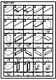
PART LIST A D E Top Panel Left Panel Right Panel Back Top Panel Front Top Rail 1PC 1PC 1PC 1PC 1PC Back Top Rail Front Middle Rail | Back Bottom Rail Bottom Panel Left Partition Panel 1PC 1PC 1PC 1PC 1PC M N Oo Right Partition Top Vertical Back Partition Back Panel Adjustable Shelf Panel Panel Panel 1PC 1PC PCs PCS PCS Middle Adjustable Drawer Front Drawer Left Panel |Drawer Right Panel| Drawer Back Panel Shelf Panel 1PC PCS PCS PCS PCS Drawer Bottom Left Door Panel | Right Door Panel Locking Caster Panel P
HARDWARE LIST #2 #3 #5 28*D30mm 2721/4 D1 1mm Cam Lock Cam Bolt Wood Dowel Long Bolt Screw 17 PCS (Extra 2) 17 PCS 45 PCS (Extra 1) 8 PCS 16 PCS (Extra 3/4" ¢ Barrel Nut Shelf Holder Knob Round Head Bolt Large Round Head Screw 8 PCS PCS 6 PCS 6 PCS 16 PCS (Extra 12mm® ¢ 3'D6mm ¢ 4*D8mm Double Magnet Magnet Round Head Allen Wrench Long Screw Screw 1PC PCS 6 PCS (Extra 1) 1PC 7 PCS (Extra (Spare Part) Short Bolt Flat Washer Spring Washer | Adjustable Leveler Pin Hinge 4 PCS (Extra) | 4 PCS (Extra 1) 4 PCS (Ex
Step 1. Insert cam bolts (part #2) into top panel (part A), left panel (part B) and right panel {part C} using fillips head screwdriver. NOTE: Do not over tighten cam bolts. Stop tightening once threads on cam bolt are no longer visible. Step 2. Attach knobs (part #8) to drawer front panels (part Q) and door panels (parts V & W) using round head bolts (part #9) and fillips head screwdriver. Attach drawer panels (parts drawer front panel (part Q) using screws (part #5) and fillips head screwdriver.
Step 3. Attach front top rail {part E) to top vertical panel {part L) using wood dowel (part #3), long screw {part #15) and fillips head screwdriver. With front top rail (part E) flat on ground, attach front middle rail (part G) and back top rail {part F) to top vertical panel (part L) using wood dowels (part #3), long screws (part #15) and fillips head screwdriver. NOTE: Please ensure screws are aligned with the per-drilled holes in top vertical panel {part L) before tightening. wa [x3 #15] x3 Step 4.
Step 5. Attach back partition panels (part M) to back top panel (part D) using wood dowels (part #3). Slide back panels (part N} into grooves of right panel (part C), back top panel (part D) and back partition panels (part Step 6. Attach back bottom rail {part H) to back partition panels (part M), back panels (part N) and right panel {part C) using wood dowels (part #3) and cam lock (part #1). NOTE: Cam locks must rotate a full 180°. See pictured insert.
Step 7. Attach left panel (part B) to assembled unit (parts using wood dowels (part #3) and cam locks (part #1). NOTE: Cam locks must rotate a full 180°. See pictured insert. 8x6 #3 x5 Step 8. Attach double magnet (part #11) and magnets (part #12) to front middle rail (part G) using round head screws (part #13) and fillips head screwdriver. Attach left partition panel {part J) and right partition panel (part K) to back top rail (part F) and front middle rail (part G) using wood dowels (part #3).
Step 9. Attach bottom panel (part |) to assembled unit (parts using wood dowels (part #3), long bolts {part #4}, barrel nuts (part #6) and Allen wrench (part #14). #3 1 x10 #4 7x8 #6 © x8 #145 x1 Step 10. CASTER INSTALLATION Attach locking casters {part X) and casters (part Y) to bottom panel (part I} using large round head screws (part #10) and fillips head screwdriver.
Step 11. LEG INSTALLATION Attach adjustable levelers (part #19) to legs (part Z). Attach legs (part Z) to bottom panel (part I) using wood dowels (part #3), flat washers (part #17), spring washers (part #18), short bolts (part #16) and Allen wrench (part #14). #14» Step 12. Carefully tum unit upright. Secure left partition panel (part J) and right partition panel {part K) to back top rail {part F} and front middle rail (part G) using long screws (part #15) and fillips head screwdriver.
Step 13. Attach top panel (part A) to assembled unit (parts using wood dowels (part #3) and cam locks (part #1). NOTE: Cam locks must rotate a full 180°. See pictured insert. #1 Ex Wessex Step 14. Attach door panels (parts placing bottom pin hinge (per-installed in door) in the per-drilled hole of bottom panel (part I). Then depress the top spring-loaded pin hinge so it can be placed in the per-drilled hole of front middle rail (part G). Place shelf holders (part #7) into desired position.