
Manual

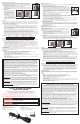

3
4
5
6
2
1
8
7
3
4
5
6
2
1
Mounting the Scope
CAUTION: Always ensure your rifle is UNLOADED, UNCOCKED and the safety is applied before fitting the
scope. Practice safe handling procedures at all times.
• The ring mounts included with this scope feature a removable recoil pin sited
underneath the rear ring. Use supplied hex wrench to adjust the pin and slot it in
to the recess of certain air rifle models to prevent the mount moving rearward under
heavy recoil. Line the recoil pin up with the rear hole on the tube. For rifles that do
not have this recess, simply remove the top half of the ring mount and unscrew the
recoil pin to remove it.
• Remove the ring mount screws (C-F) and lift the scope from the mounts.
• Loosen the mounting screws (A-B) on the base of the mounts.
• Tighten the ring base mounting screws.
• Mount the front base and place the scope on the rail with the ocular lens toward the
rear of the gun.
• Put the rifle to your shoulder in your natural shooting position and adjust the scope’s eye relief until you
achieve a full field of view.
• When you have found the ideal eye relief rotate the scope so the reticle cross hairs are vertical and perpendicular to
the rifle.
• Replace the ring mounts and ring mount screws.
• Tighten the screws on the ring to ensure a firm grip on the scope. NOTE: Do not over tighten the screws as
you could cause damage to the scope body.
Adjusting Parallax and Focus
• Aim the scope at your target.
• Adjust the fast focus eyepiece until both the crosshair and the target are in sharpest focus.
• Rotate the parallax adjustment ring to the desired distance setting until the target is in the sharpest focus and
the center of the crosshair stays on the target while you examine the image by slightly moving your head.
Variable Power Adjustments
To change the magnification, simply rotate the magnification ring to align the desired magnification with the index dot.
CenterPoint Precision Optics
7629 Routes 5 & 20
East Bloomfield, NY 14443
www.centerpointoptics.com
1-866-726-1122 CP394AO-515
CP394AO / CP394AODP
OWNER'S MANUAL
READ ALL INSTRUCTIONS AND WARNINGS IN THIS
MANUAL BEFORE USING THIS SCOPE
Maintenance
• Take care not to drop or knock the scope once it is zeroed.
• Keep the protective lens covers in place when the scope is not being used.
• Store the scope in a cool dry place when not in use.
• Be careful to avoid contact with acid, alkaline or corrosive chemicals.
• Do not attempt to lubricate any part of the scope.
• Do not disassemble the scope. Do not loosen or remove any screws or parts. Any such or similar actions will
void the warranty.
• Wipe the lens with a clean flannel cloth to keep it clean and dry. Do not use finger or finger nail to touch or clean lenses.
• Use only a clean flannel cloth for cleaning.
1. Magnification Ring 5. Parallax Adjustment Ring
2. Fast Focus Eyepiece 6. Objective lens
3. Ocular Lens 7. Removable Flip Open Lens Covers
4. Elevation (vertical) Adjustment 8. Windage (horizontal) Adjustment
LIMITED LIFETIME WARRANTY ON CENTERPOINT SCOPES
Your CenterPoint scope is warranted to be free of defects in materials and workmanship for the lifetime
of the original owner. This warranty does not cover damages due to fair wear and tear, failure to provide
routine maintenance, and does not include batteries or accessories. This warranty lasts as long as the
original purchaser owns the product, and is not transferable. In the event of a defect under this warranty,
we will, at our option, repair or replace the product provided our inspection indicates that an original
defect exists. CenterPoint reserves the right to replace any product which is no longer available with a product
of comparable value and function. If CenterPoint determines the repair is not covered under the warranty
guidelines, there could be a charge to you for the repair. This is a limited warranty and does not cover damages
caused by misuse, improper handling or installation or maintenance provided by someone other than a
CenterPoint Authorized Service Station.
This limited warranty does not include consequential damages, incidental damages, or incidental expenses,
including damage to property or any other expense. CenterPoint disclaims any implied warranties. Some
states do not allow the exclusion or limitation of incidental or consequential damages, or allow limitations on
implied warranties so the above limitations or exclusions may not apply to you. This warranty gives you specific
legal rights, and you may also have other rights which vary from state to state and country to country.
WARRANTY CLAIMS/ REPAIR SERVICE
If your scope needs repair, call CenterPoint Customer Service at 1-800-726-1122 or visit our web site at
www.centerpointoptics.com DO NOT ATTEMPT TO DISASSEMBLE IT! Any disassembly or modification not
performed by an Authorized Service Station will void the warranty.
USA
Customers: Please contact CenterPoint before shipping your product. Include with product your name, address,
description of problem, phone number and copies of sales receipt and warranty. A check or money order in the
amount of $10.00 to cover the cost of postage and handling is also required. Package and return to CenterPoint,
Crosman Corporation, 7629 Rts. 5 & 20, E. Bloomfield, NY 14443. CenterPoint will not assume any responsibility for
any loss or damage incurred in shipping.
Canadian Customers
: Contact Crosman Parts and Service at (705) 749-0206 before shipping your product.
Follow packaging and shipping procedures above and send to Crosman Parts & Service Depot, 611 Neal
Drive, Peterborough, Ontario K9J 6X7 Canada. Shipping and handling costs may apply.
Other International Customers
: Please return product to your nearest distributor. If you do not know your distributor,
please call 585-657-6161 and ask for our International Department for assistance. Shipping and handling costs may
apply.
Zeroing the Scope
The purpose of zeroing the scope is to ensure that the scope is aligned with the
impact point of the pellet or bullet from the rifle. Before zeroing the scope, read the
following adjustment knob instructions carefully.
• The windage and elevation adjustment knobs have a unique locking screw
design. A hex wrench is provided with the scope.
• IMPORTANT: Refer to Figure 1 for the correct way to hold down the outer
rim of the adjustment knob whenever you use the hex wrench to
tighten/loosen the locking screw.
Zero Locking
• Firmly hold down the windage or elevation adjustment knob as shown in Fig 1. Use the hex wrench to turn
the locking screw clockwise until tight. Do not over-tighten.
• When the locking screw is completely tightened down, the windage or elevation adjustment knob is
"locked". The knob will not rotate, preventing any accidental movement to lose zero. (W/E knobs are at
"locked position for a new scope.)
8
Range Estimating (For Mil-Dot Reticles ONLY)
Range estimating requires common knowledge/experience about your target's actual width or height. Use the the
Mil-Dot instruction card in the scope box for the specific formula for your scope model.
BUYER AND USER HAVE THE DUTY TO OBEY ALL LAWS ABOUT THE USE AND OWNERSHIP OF THIS
SCOPE.
All CenterPoint scopes are constructed with high quality precision machined parts. The rugged one piece tube
construction works for all terrains and weather. The scope is precision machined to exact tolerances from aircraft-
grade aluminum alloy.
Learning the parts of your scope
Learning the names of the parts of your new scope will help you to understand your owner's manual.
Direct viewing of the sun can cause permanent eye damage. Do not
attempt to view the sun through this riflescope or any other optical
instrument.
WARNING:
Always follow all rules of firearm and gun safety.
WARNING:
Zeroing
Firmly holding down the windage or elevation knob as shown on Fig. 1, use the hex wrench to turn the Locking
Screw counter-clockwise until the "adjustment line" appears (Fig. 2-2). When the knob base sits at this adjustment
line, windage and elevation can be rotated for zeroing.
• Place a target 100 yards away.
• Ideally use a steadying device such as a bipod or shooting stand, set the scope at the highest magnification,
aim at the center of the target and fire a test shot, if safe to do so.
• If the impact point of the pellet or bullet is exactly in the center of the target then the scope is zeroed. If it is not, you
will need to adjust the reticle using the elevation and/or windage adjusters.
•V
ertical Adjustment (Elevation) - Use your fingers to turn the adjusting knob as required. One click in either
direction equals approximately 1/4 inch at 100 yards.
• Horizont
al Adjustment (Windage) - Use your fingers to rotate the adjusting knob as required. One click in
either direction equals approximately 1/4 inch at 100 yards.
• Having adjusted the windage and elevation as required, fire, if safe to do so, another test shot. Keep
adjusting and test firing until the test shot impacts on the center of the target when the reticle is on the
center of the target. This is vital for accurate shooting.
Note: Each click of adjustment moves the impact point by the amount shown in the table below.
Zero Resetting
Once your scope is zeroed, the "0" marking may not be facing you at the original center position. Optionally, you
can rotate "0" to the centerline using the following steps.
• Firmly holding down the W/E knob as shown in Fig. 1, use the hex wrench to turn the locking screw counter-
clockwise until the "zero resetting line" appears (Fig. 2-3).
• When the knob base sits at this" zero resetting line", the W/E knob has been disengaged and rotating the
knob will not affect zero. You can re-position the "0" mark to the centerline.
• When complete with scope zeroing, followed by optional zero resetting, be sure to LOCK ZERO by following
the steps in zero locking.
@ 50yds @ 100yds @ 200yds @ 300yds
1/8” 1/4” 1/2” 3/4”
EL COMPRADOR Y EL USUARIO TIENEN EL DEBER DE OBEDECER TODAS LAS LEYES RELATIVAS AL
USO Y PROPIEDAD DE ESTA MIRA TELESCÓPICA.
Todas las miras telescópicas CenterPoint están construidas con piezas mecanizadas de precisión de alta calidad. La
resistente construcción de tubo de una pieza funciona para todos los terrenos y climas. La mira telescópica está
mecanizada con precisión a tolerancias exactas a partir de aleación de aluminio de grado de aeronave
.
Aprendiendo las partes de su mira telescópica
Aprendiéndose los nombres de las partes de su nueva mira telescópica le ayudará a entender su manual del propietario.
Modelo CP394AO / CP394AODP
MANUAL DEL PROPIETARIO
LEA TODAS LAS INSTRUCCIONES Y ADVERTENCIAS DE ESTE
MANUAL ANTES DE USAR LA MIRA
La visión directa del sol puede ocasionar daños permanentes al ojo.
No intente ver el sol a través de esta mira telescópica del rifle ni de
ningún otro instrumento óptico.
Advertencia:
Siempre siga todas las reglas de seguridad para armas de fuego.
Advertencia:
1. Anillo de aumento 5. Selector de ajuste de paralaje lateral
2. Ocular de enfoque rápido 6. Lente del objetivo
3. Lente ocular 7. Tapas de los lentes removibles con bisagra
4. Ajuste de elevación (vertical) 8. Ajuste de compensación de viento (horizontal)
Montaje de la mira telescópica
PRECAUCIÓN: Antes de instalar la mira telescópica, asegúrese siempre de que el rifle esté DESCARGADO Y
DESAMARTILLADO y que el seguro esté aplicado. Practique procedimientos de manipulación seguros en todo
momento.
• Las monturas de anillo incluidas con esta mira telescópica tienen un perno de
retroceso removible situado debajo del anillo posterior. Use la llave allen incluida
para ajustar el perno y colocarlo dentro del hueco de algunos modelos de rifle
para evitar que la montura se mueva hacia atrás cuando hay un fuerte retroceso.
Alinee el tornillo de fijación con el orificio posterior del tubo. En el caso de los
rifles que no tienen este hueco, sólo debe quitar la mitad superior de la montura
de anillo y destornillar el perno de retroceso para quitarlo.
• Quite los tornillos de la montura de anillo (C-F) y levante la mira telescópica de las
monturas.
• Afloje los tornillos de montaje (A-B) en la base de las monturas.
• Apriete los tornillos de montaje de la base del anillo.
• Monte la base delantera y coloque la mira telescópica en el riel con el lente ocular hacia la parte posterior del arma.
• Colóquese el rifle en el hombro en su posición natural de disparo y ajuste la distancia del ojo hasta que consiga una
vista de todo el campo.
• Cuando haya encontrado la distancia del ojo ideal, gire la mira telescópica de modo que las marcas en cruz de la
retícula estén verticales y perpendiculares al rifle.
• Vuelva a colocar las monturas de anillo y los tornillos de las monturas de anillo.
• Apriete los tornillos del anillo para asegurar un agarre firme de la mira telescópica. NOTA: No apriete los tornillos en
exceso ya que podría ocasionarle daños al cuerpo de la mira telescópica.
Ajuste del paralaje y del foco
• Apunte la mira telescópica a su blanco.
• Ajuste el ocular de foco rápido hasta que ambas líneas de la cruz y del blanco estén enfocados de la forma
• Gire el anillo de ajuste de paralaje al valor de distancia deseado hasta que el blanco esté enfocado de la forma más
nítida y el centro de la cruz de la retícula permanezca en el blanco mientras usted examina la imagen
moviendo ligeramente la cabeza.
Ajustes de potencia variable
Para cambiar el aumento, simplemente gire el anillo de aumento para alinear el aumento deseado con el punto de índice.
7
locking
Screw
C/D
E/F
B
A
C/D
E/F
B
A
Model Modelo
Modèle
CP394AO CP394AO
Magnification Aumento
Grossissement
3x-9x 3x-9x
Objective Diameter (mm) Diámetro del objetivo (mm)
Diamètre de l'objectif (mm)
40 40
Reticle
Reticle
Reticle
Mil-Dot Duplex
Exit Pupil (mm) Pupila de salida (mm)
Pupille de sortie (mm)
10.0 - 4.4 10.0 - 4.4
Eye Relief (inches) Distancia del ojo (pulgadas)
Dégagement oculaire (pouces)
3.3 3.3
Field of View (@ 100yds) Campo de visión (pies a 100 yardas)
Champs de vision (pi @ 91.44 m)
39.0’ - 13.0’ 39.0’ - 13.0’
Tube Diameter (inches) Diámetro del tubo (pulgadas)
Diamètre du tube (pouces)
1 1
Length (inches) Longitud (pulgadas)
Longueur (pouces)
13.5 13.5
Weight (ounces) Peso (onzas)
Poids (onces)
22.6 22.6
W/E Adjust Click Value Valor de clic de ajuste de viento y elevación
Cadran-indicateur W/E (dérive/hauteur)
1/4 MOA 1/4 MOA
Parallax Setting (yds) Ajuste de paralaje (yardas)
Réglage de la parallaxe
5
to infinity
5
to infinity
Caractéristiques
EspecificacionesSpecifications