Installation Guide Cross Hydronic Manifold System TM
STEP 1 Choose a position to mount the manifold. POSITION OPTION 1: Upwards STEP 2 Connect tubing loops and boiler piping. To boiler To boiler POSITION OPTION 2: Downwards Secure manifold to the wall using rigid anchors or mounting screws. IMPORTANT! Hand tighten only.
STEP 3 Fill and purge the manifold. STEP 4 Attach Cross motor carriage and control. NOTE! To ensure proper system performance, it is important to purge the system. A Connect garden hose to supply hose bib connection on manifold, and hook up the other end to house pressure. Screw handles in on sides. B Connect garden hose to return manifold, and place the other end to drain or bucket.
STEP 5 Connect thermostat wire to Cross Control and plug into outlet. CONNECTING MULTIPLE ZONES USING A SINGLE THERMOSTAT NOTE When using multiple loops with one thermostat, jumper the whites together. E A B C D A 3-Wire Thermostats: Red to Left White to Right Black to Common B 2-Wire Thermostats: Ignore common terminal block C To optional 24V Relay D N/O dry contact for boiler (TT) terminals E Cross power supply Insert Zone Index card into the back slot.
EASY-CHANGE FITTINGS 1/2 Universal PEX crimp fitting For PEX, PEX-AL-PEX, PE-RT. 3/4 Universal PEX crimp fitting For PEX, PEX-AL-PEX, PE-RT. 1/2 Copper adaptor For ProPress fitting or copper sweat fitting. 3/4 Copper adaptor For ProPress fitting or copper sweat fitting.
INSTALLATION OPTIONS Radiant Heat Radiator + Ultra-Fin Radiant System Radiators Ultra-Fin Radiant System
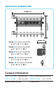
MANIFOLD DIMENSIONS Height (H) Length (L) Cross 4 (4 zone manifold) L 18 5/8” H 15 3/4” W 6” Width (W) Cross 6 (6 zone manifold) L 23” H 15 3/4” W 6” Cross 8 (8 zone manifold) L 27 5/8” H 15 3/4” W 6” Cross 10 (10 zone manifold) L 31 5/8” H 15 3/4” W 6” Cross 12 (12 zone manifold) L 36” H 15 3/4” W 6” Contact Information CALL TOLL-FREE 1 888 565 2267 FAX TOLL-FREE 1 888 565 2228 www.crossmanifold.com EMAIL info@crossmanifold.com OFFICE HOURS ULTRA-FIN INC.