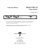
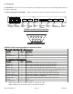
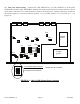
Model 1582-14 Instruction Manual Data Switch June 2009 Rev. A AUTO AUTO CH 2 CH 1 MAN ALM ONLINE MANUAL SELECT MODEL 1582 SWITCH B SWITCH A ON- ALM REM RESET LINE CH 2 CH 1 MAN ALM ONLINE MANUAL SELECT ON- ALM REM RESET LINE 1 2 CROSS TECHNOLOGIES, INC. POWER Data, drawings, and other material contained herein are proprietary to Cross Technologies, Inc., but may be reproduced or duplicated without the prior permission of Cross Technologies, Inc. for purposes of operating the equipment.
INSTRUCTION MANUAL MODEL 1582-14 DATA SWITCH TABLE OF CONTENTS Warranty 1.0 General 1.1 Equipment Description 1.2 Technical Specifications 2.0 Installation 2.1 Mechanical 2.2 Rear Panel Inputs and Outputs 2.3 Front Panel Controls and Indicators 2.4 PC Board Settings 2.4.1 On-Card Jumpers 2.4.2 On-Card Settings 2.5 Time Out Alarm Settings 2.6 Switch Mode Setup 2.7 Operation 2.
MODEL 1582-14 Data Switch 1.0 General 1.1 Equipment Description - The 1582-14 Data Switch has two independent switches (A and B) in a single 1 3/4” chassis. Each switch provides Auto, Manual, or Remote relay switching between CH1 and CH2 RS422 clock or data signals on pins 3 and 8 with pin 5 ground and the other pins not connected. Clock or data transitions are detected from pin 3 and a clock (or data) presence alarm is activated if transitions are lost for a set period of time.
1.2 Technical Specifications TABLE 1.0 1582-14 Data Switch Specifications* Data Characteristics Input/Output RS422 Data rate 128 kbps, max Connectors, data DB9, female Pins Switched 3, 8 Ground pin 5 Switch Characteristics Type Relay, non-latching Isolation >40 dB Switch after alarm 0.1 to 0.9 seconds (selectable in 0.
2.0 Installation 2.1 Mechanical - The 1582-14 is rack mounted by attaching the front panel to a rack through the four holes at the edges of the panel. 2.2 Rear Panel Inputs and Outputs - Figure 2.0 shows the input and output connectors on the rear panel. AC 1 AC 2 GN D AC1 AC2 POWER IN 1 POWER IN 2 1.5 A FUSE 1.
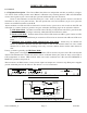
2.3 Front Panel Controls and Indicators - The following are the front panel controls and indicators. SWITCH B SWITCH A AUTO MAN ALM ONLINE AUTO CH 2 CH 1 MANUAL SELECT ON- ALM LINE CH 2 CH 1 REM RESET MAN ALM ONLINE MANUAL SELECT ON- ALM LINE 1 REM RESET 2 POWER FIGURE 2.2 1582-14 Front Panel Controls and Indicators TABLE 2.
2.4 PC Board Settings 2.4.1 On-Card Jumpers NOTE: Dot position means jumper goes from center pin to the pin nearest the dot on the PCB. Also the first jumper designation is for switch A (J1) and the second is for switch B (J101). JP1, JP101 - 3-pin jumper that works with JP3, JP103 In the dot position when channel 1 alarms the 1582-14 will switch to channel 2 until channel 2 alarms. At this point, if channel 1 is still in alarm, the switch will stay on channel 2.
JP10, JP110 - CH1 Clock Detection Filter- 3-pin jumper that filters out non-data spikes if clock is not present. Non-dot position - presence of clock is detected on the first few positive transition of clock from CH1. Dot position - presence of clock is detected after about 1 ms of positive transitions of clock from CH1. JP10,110 normal position - Non-dot. JP15, JP16, JP17, JP18 - Alarm clock frequency 3-pin jumper FACTORY SET to provide clock for the time out alarm circuitry. DO NOT ADJUST THESE! Figure 2.
2.5 Time Out Alarm Settings - Switches S4 (CH2, SWITCH A), S5 (CH1, SWITCH A), S104 (CH2, SWITCH B), and S105 (CH1, SWITCH B) determine the length of time after clock is removed before a loss of clock alarm is indicated. Use a small flat blade screwdriver or tuning tool to carefully adjust these switches to the desired length in 0.1 second increments (position 1 = 0.1 seconds, position 2 = 0.2 seconds, etc.). (see Figure 2.
2.6 Switch Mode Setup - The following gives the switch mode settings of the on board controls that can be changed in the field: SWITCH A JP1, JP2, JP3, JP4; S3; SWITCH B - JP101, JP102, JP103, JP104, S103 (Section 2.3, Figure 2.3). All shown with external alarm = ground. 1) CH1 Prime Mode - Switches from CH1 to the CH2 only if CH1 alarms and CH2 is good.
2.8 Environmental Use Information A. Rack-Mounting - To mount this equipment in a rack, please refer to the installation instructions located in the user manual furnished by the manufacturer of your equipment rack. B. Mechanical Loading - Mounting of equipment in a rack should be such that a hazardous condition does not exist due to uneven weight distribution. C.
CROSS TECHNOLOGIES, INC. 6170 Shiloh Road Alpharetta, Georgia 30005 (770) 886-8005 FAX (770) 886-7964 Toll Free 888-900-5588 WEB: www.crosstechnologies.com E-MAIL: info@crosstechnologies.