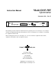
Model 2015-58T Instruction Manual Upconverter November 2012, Rev. D IF MONITOR MODEL 2015 RF MONITOR UPCONVERTER F = 5950.000 G = +10.0 REMOTE POWER MUTE ALARM MENU CROSS TECHNOLOGIES INC. EXECUTE Data, drawings, and other material contained herein are proprietary to Cross Technologies, Inc., but may be reproduced or duplicated without the prior permission of Cross Technologies, Inc. for purposes of operating the equipment. Printed in USA. When ordering parts from Cross Technologies, Inc.
INSTRUCTION MANUAL MODEL 2015-58T Upconverter TABLE OF CONTENTS PAGE Warranty 1.0 General 1.1 Equipment Description 1.2 Technical Characteristics 1.3 Monitor & Control Interface 1.4 Environmental Use Information 2.0 Installation 2.1 Mechanical 2.2 Rear Inputs & Outputs 2.3 Front Panel Controls & Indicators 2.4 Operation 2.5 Menu Settings 2 3 3 4 5 7 8 8 9 9 10 11 WARRANTY - The following warranty applies to all Cross Technologies, Inc. products. All Cross Technologies, Inc.
MODEL 2015-58T Upconverter 1.0 General 1.1 Equipment Description The 2015-58-T Upconverter converts 70 ±18 MHz to 5.845 to 6.725 GHz in 125 kHz steps with low group delay and flat frequency response. Synthesized local oscillators (LO) provide low phase noise and ±1.0 ppm stability frequency selection. Push button switches select the RF frequency, gain, and other parameters.
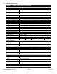
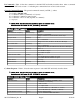
1.2 Technical Characteristics TABLE 1.1 2015-58-T Upconverter Specifications* Input Characteristics Impedance / Return Loss Frequency 75Ω / 20 dB 70 ±18 MHz Input Level -30 to -10 dBm Noise Figure 20 dB typical; 25 dB maximum, +30 dB gain Output Characteristics Impedance / Return Loss Frequency Output Level Output 1 dB Compression 50Ω / 20 dB Typical, 18 dB min. 5.845 to 6.725 GHz -20 to 0 dBm +10 dBm Channel Characteristics Gain Range / Stability Spurious Response Intermodulation +10.0 to +30.
1.3 Monitor and Control Interface A) Remote Serial Interface Protocol - RS-485, RS-422 or RS-232C (selectable), 9600 baud rate, no parity, 8 data bits, 1 start bit, 1 stop bit.
B) Commands - Table 1.2 lists the commands for the 2015-58T and briefly describes them. After a command is sent the 2015-58T sends a return “>” indicating the command has been received and executed. General Command Format - The general command format is {aaCND...
1.4 Environmental Use Information A. Rack-Mounting - To mount this equipment in a rack, please refer to the installation instructions located in the user manual furnished by the manufacturer of your equipment rack. B. Mechanical Loading - Mounting of equipment in a rack should be such that a hazardous condition does not exist due to uneven weight distribution. C.
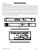
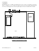
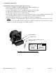
2.0 Installation 2.1 Mechanical The 2015-58T consists of one RF/Controller PCB which is housed in a 1 RU (1 3/4 inch high) by 16 inch deep chassis. A switching, ± 12, +24, +5 VDC power supply provides power for the assembly. The 2015-58T can be secured to a rack using the 4 holes on the front panel. Figure 2.1 shows how the 2015-58T is assembled. POWER SUPPLY PCB FIGURE 2.1 2015-58T Mechanical Assembly 2015-58T Manual_Rev.
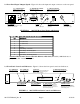
2.2 Rear Panel Input / Output Signals - Figure 2.2 shows the input and output connectors on the rear panel. J18 - 10 MHz REF OUTPUT 10 MHz reference output, 3 ± 3 dBm, 50/75 ohms BNC (female) connector. J10 - MONITOR AND CONTROL DB9 female connector. see Table 2.1. J3 - 10 MHz EXT REF INPUT 10 MHz external reference input, 3 ± 3 dBm, 50/75 ohms, BNC (female) connector.
2.4 Installation / Operation 2.4.1 Installing and Operating the 2015-58T Upconverter 1. Connect a -30 dBm to -10 dBm, 70 MHz signal to IF IN, J4 (Figure 2.2) 2. Connect RF OUT, J5, to the external equipment. 3. Connect 100- 240 ±10% VAC, 47 - 63 Hz to AC input on the back panel. 4. Set the desired output frequency (See Section 2.5 Menu Settings). 5. Set the input level (See Section 2.5 Menu Settings). 6. Set the gain so that the output level is always within the range of -20 to 0 dBm.
2.5 Menu Settings 2.5.1 Functions - This section describes operation of the front panel controls. There are three operator switches, the LCD display and alarm indicator LEDs. All functions for the equipment are controlled by these components. The functions are (see Figure 2.5): Power Up Normal Display Menu 1 Menu 2 Menu 3 Menu 4 Menu 5 Menu 6 Menu 7 Menu 8 Frequency in MHz Input Level in dBm (-30 to -10) Gain in dB (+10.0 to +30.
2.5.2. Power On Settings NOTE: The last status of a unit is retained even when power is removed. When power is restored, the unit will return to it's previous settings. When power is first applied, the LCD display goes through three steps. 1.The LCD goes black to show all segments are functioning. 2.The software version will be displayed. REV 1.00 3.The present frequency, gain, and selected RF output of the upconverter is shown. F = 5950.000 G = +10.
2.5.4 Frequency Changes At any time during the modification process, if you have made a mistake and do not wish to save the changes you have made, do not press the Menu/Execute switch; simply do nothing for approximately 12 seconds, and the system will return to the normal operating mode or scroll to “R” and push the menu/Execute switch and select “NO” in the “SAVE SETTINGS?” window. To change the FREQUENCY: 1.Operate the Menu/Execute switch until you get to the menu item you want to change see Figure 2.
2.5.5 Gain Changes When you get to this menu note that the gain changes will be made as you make them but if you do not wish to save the changes you have made, scroll to “R” and push the menu/Execute switch and select “NO” in the “SAVE SETTINGS?” window or do not press the Menu/Execute switch; simply do nothing for approximately 12 seconds, and the system will return to the normal operating mode.
2.5.5 Alarm Indications An alarm condition for will occur if the local oscillator phase lock loop (PLL) comes out of lock. The Mute LED will light if you select to mute the Tx Signal and the Remote LED will light when you select the Remote mode. ON POWER UP REV 1.00 Power Up NORMAL DISPLAY F = 5950.000 G = +10.0 Normal Display PUSH BUTTON PUSHING MENU/EXECUTE SEQUENCE F = 5950.
CROSS TECHNOLOGIES, INC. 6170 Shiloh Road Alpharetta, Georgia 30005 (770) 886-8005 FAX (770) 886-7964 Toll Free 888-900-5588 WEB www.crosstechnologies.com E-MAIL info@crosstechnologies.com Printed in USA 2015-58T Manual_Rev.