
Instruction manual
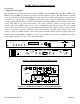

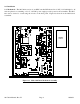
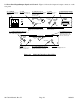

2.2 Rear Panel Input/Output Signals and Control - Figure 2.2 shows the input and output connectors on the
rear panel.
AC
GND
J18J2
RF IN
10 MHZ REF
OUTPUT
AC1 - POWER IN
AC input for switching power
supply. 100-240 ± 10% VAC,
47-63 Hz.
J2 - RF IN
950-1525 MHz input, -60
to -10 dBm, see Table 2.2.
J1 - IF OUT
70 MHz output, -10 to 0
dBm, See Table 2.2.
J10
AND
MONITOR
CONTROL
J10 - MONITOR AND CONTROL
DB9 female connector. see Table
2.1.
RF OUT
J4 J5J3
10 MHZ
IF IN
EXT REF
J3 - 10 MHz EXT REF INPUT (Option -E)
10 MHz external reference input, 0 ± 3 dBm, 75
ohms, BNC female connector.
J5 - RF OUT
950-1525 MHz output,
-35 to -15 dBm out, see Table 2.2.
J4 - IF IN
70 MHz input, -40 to -10
dBm in, see Table 2.2.
SSPB FUSE
F2
F2 - SSPB FUSE (option -V)
2.5A, Fast Blo, 1/4” Fuse;
installing fuse places +24
VDC, 2.5 amp, max. on the
RF OUT (J5 center pin).
F1 - LNB FUSE (option -L)
0.5A, Fast Blo, 1/4” Fuse; installing
fuse places +24 VDC, 0.4 Amps,
max. on the RF IN
(J2 center pin).
LNB FUSE
F1
DOWNCONVERTER
UPCONVERTER
J1
IF OUT
DS8
VDC on RF
DS7
VDC on RF
INPUT
DS7 - SSPB ALARM LED (option -V)
Lights yellow when +24 VDC SSPB voltage is
present on RF OUT, J5, center pin.
DS8 - LNB ALARM LED (option -L)
Lights yellow when +24 VDC LNB
voltage is present on RF IN, J2, center
pin.
J18 - 10 MHz REF OUTPUT (option -E)
10 MHz reference output. 75Ω BNC
female connector.
15
23
4
6
78
9
Figure 2.1 Model 2017-03A Rear Panel I/O’s
2017-03A Manual, Rev. H Page 10 10/08/13