
Instruction manual

2.4 Installation / Operation
2.4.1 Installing and Operating the 2017-03A, Upconverter Section
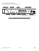
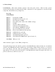
1.) Connect a -40 dBm to -10 dBm signal to IF In, J4 (Figure 2.1).
2.) Connect the RF OUT, J5, to the external equipment.
3.) Connect 100 - 240 (±10% VAC), 47 - 63 Hz to AC on the back panel.
4.) Set the desired output frequency (See Section 2.5 Menu Settings).
5.) Set the input level (See Section 2.5 Menu Settings).
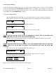
6.) (option V) To power the SSPB (+24 VDC, 2.5 amps max.) from the 2017-03A install a 2.5 amp
1/4” fuse in F2.
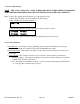
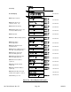
7.) Be sure DS6 (green, DC Power) is on and DS2 (red, Alarm) is off (Figure 2.2)
CAUTION!!! INSTALLING A FUSE IN F2 PUTS +24 VDC, 2.5 AMP POWER ON THE CENTER PIN
AND MAY DAMAGE EQUIPMENT IF IMPROPERLY CONNECTED TO EQUIPMENT THAT
CANNOT HANDLE THIS VOLTAGE OR HAS A DC PATH TO GROUND.
2.4.2 Installing and Operating the 2017-03, Downconverter Section
1.) Connect a -60 dBm to -10 dBm signal to RF In, J2 (Figure 2.1).
2.) Connect the IF OUT, J1, to the external equipment.
3.) Connect 100-240 ±10% VAC, 47 - 63 Hz to AC on the back panel.
4.) Set the desired input frequency (See Section 2.5 Menu Settings).
5.) Set the gain to get an output level in the 0 to -20 dBm range (See Section 2.5 Menu Settings).
6.) (option -L) To power the LNB (+24 VDC, 0.5 amps, max.) from the 2017-03A install a
1 amp 1/4” fuse in F1.
CAUTION!!! INSTALLING A FUSE IN F1 PUTS +24 VDC, 0.5 AMP POWER ON THE CENTER PIN
AND MAY DAMAGE EQUIPMENT IF IMPROPERLY CONNECTED TO EQUIPMENT THAT
CANNOT HANDLE THIS VOLTAGE OR HAS A DC PATH TO GROUND.
7.) Be sure DS6 (green, DC Power) is on and DS2 (red, Alarm) is off (Figure 2.2).
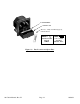
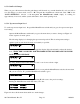
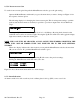
8.) AC Fuse - The fuse is a 5 mm X 20 mm, 2 amp slow blow (Type T) and is inserted in the far slot
in the drawer below the AC input as shown in Figure 2.3. There is a spare fuse in the near slot.
If a fuse continues to open, the power supply is most likely defective.
2017-03A Manual, Rev. H Page 13 10/08/13