
Instruction manual
2.5 Menu Settings
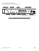
2.5.1 Functions - This section describes operation of the front panel controls. There are three operator
switches, the LCD display and alarm indicator LEDs. All functions for the equipment are controlled by these
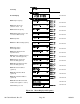
components. The functions are (see Figure 2.2):
Power Up
Normal Display
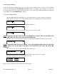
Menu 1 Up Frequency in MHz
Menu 2 Up Input Lvl (Set from -45 to -15)
Menu 3 Down Frequency in MHz
Menu 4 Down Gain (set 0 to +50 for -10 to 0 dBm out range)
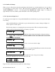
Menu 5 Up Mute
Menu 6 Set Unit to Remote Operation
Menu 7 Set Downconverter Spectrum Sense
Menu 8 Select External 10 MHz Ref (option E)
Menu 9 Upconverter Reference Out (option E)
Menu 10 Downconverter Reference Out (option E)
Menu 11 Set RS-485 mode (option Q)
Menu 12 Set RS-485 address (option Q)
Menu 13 View PCB Temperature (option T)
Menu 14 View LNB and/or SSPB Current (options L and/or V)
Save Menu When go to end
Alarm indications appear on the LEDs (see figure 2.2).
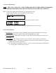
All program changes must start with the operation of the Menu/Execute switch and must also end with the
operation of the Menu/Execute switch verified by the “Save Settings?” Menu. If this sequence is not followed,
none of the changes will take effect. If programming is initiated and no operator action takes place for
approximately 12 seconds (before the final press of the Menu/Execute switch) the display will revert to its
previous status and you will need to start over.
2017-03A Manual, Rev. H Page 15 10/08/13