
Instruction manual

2.4 Operation
2.4.1 Installing and Operating the 2016-03A Downconverter
1. Connect a -20 dBm to -70 dBm signal to RF IN, J2 (Figure 2.2)
2. Connect the IF OUT, J1, to the external equipment
3. Connect 100-240 ±10% VAC, 47 - 63 Hz to AC on the back panel.
4. Set the input frequency (See Section 2.5 Menu Settings).
5. Set the gain for +00.0 to +50.0 dB (See Section 2.5 Menu Settings).
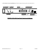
6. Be sure DS6 (green, DC Power) is on and DS3 (red, Alarm) is off (Figure 2.3).
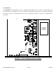
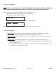
7. Option -L only - To insert LNB +24 VDC on the RF center pin install 0.5A fast blo fuse in F1 and
check that DS8 lights yellow (Figure 2.1)
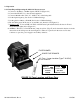
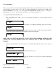
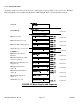
8. AC Fuse - The fuse is a 5 mm X 20 mm, 2 amp slow blow (Type T) and is inserted in the far slot in the
drawer below the AC input as shown in Figure 2.4. There is a spare fuse in the near slot. If a fuse
continues to open, the power supply is most likely defective.
FUSE DRAWER
SPARE FUSE DRAWER
AC Fuse - 2 amp slow blow (Type T 2A GDC),
5 mm X 20 mm
~
INPUT
100-240± 10%VAC
47-63 Hz
2A MAX
FUSE
TYPE T 2A GDC
250 VOLT
FOR 100 - 240 V~
~
FIGURE 2.4 Fuse Location and Spare Fuse
2016-03A Manual, Rev A Page 12 11/25/08