Model 2017-14 Instruction Manual UHF, L-Band, Up/Downconverter January 2013, Rev. 0 RF MONITOR DOWNCONVERTER MODEL 2017 RF MONITOR UP/DOWNCONVERTER --------- UPCONV-------UPCONVERTER U U > L D L > U G = 10.0 G = 25.0 INT ------- DNCONV-------MENU CROSS TECHNOLOGIES INC. EXECUTE ALARM REMOTE POWER MUTE ALARM Data, drawings, and other material contained herein are proprietary to Cross Technologies, Inc.
INSTRUCTION MANUAL MODEL 2017-14 UHF, L-Band, Up/Downconverter TABLE OF CONTENTS Warranty 1.0 General 1.1 Equipment Description 1.2 Technical Characteristics 1.3 Monitor & Control Interface 1.4 Environmental Use Information 2.0 Installation 2.1 Mechanical 2.2 Rear I/O’s 2.3 Front Panel Controls, Indicators 2.4 Operation 2.5 Menu Settings PAGE 2 3 3 4 5 8 9 9 10 12 13 15 WARRANTY - The following warranty applies to all Cross Technologies, Inc. products. All Cross Technologies, Inc.
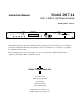
MODEL 2017-14 UHF, L-Band, Up/Downconverter 1.0 General 1.1 Equipment Description The 2017-14 UHF, L-band Up/Downconverter converts 0.2-0.4 GHz to 1.2-1.4 GHz (Up) and 1.2-1.4 GHz to 0.2-0.4 GHz (Down). Multi-function switches select the gain (0 to +30 dB range for the Upconverter and Downconverter), and other parameters. Front panel LEDs provide indication of DC power (green), PLL alarm (red), remote operation (yellow), and Upconverter mute (yellow).
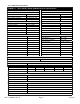
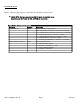
1.2 Technical Characteristics TABLE 1.0 2017-14 UHF, L-Band, Up/Downconverter Specifications* UPCONVERTER DOWNCONVERTER Input Characteristics (UHF, L) 50Ω / 14 dB Impedance/Return Loss 50Ω / 14 dB Input Characteristics (L, UHF) Impedance/Return Loss Frequency Noise Figure, maximum Input Level Range 0.2 to 0.4 GHz 20 db @ max. gain -40 to -25 dBm Frequency Noise Figure, maximum Input Level Range 1.2 to 1.4 GHz 15 @ max.
1.2 Technical Characteristics continued... Available Options: UHF, L-Band Up/Downconverter - E1 External 10 MHz Reference / Auto Switch -H High stability (±0.
1.3 Monitor and Control Interface A) Remote serial interface Protocol: RS-232C, 9600 baud rate, no parity, 8 data bits, 1 start bit, and 1 stop bit.
B) Status Requests Table 1.1 lists the status requests for the 2017-14 and briefly describes them. * PLEASE NOTE: The two character {aa}(00-31) prefix, in the table below, should be used ONLY when RS-485, (OPTION-Q), is selected. Table 1.1 2017-14 Status Requests Re equests Command Syntax* Description Command Status {aaS1} Returns {aaS1bbbcccdefg} where: • bbb = Upconverter Gain (000 to 300) 00.0 to 30.0 dB • ccc = Downconverter Gain (000 to 300) 00.0 to 30.
C) Commands Table 1.2 lists the commands for the 2017-14 and briefly describes them. After a command is sent the 2017-14 sends a return “>” indicating the command has been received and executed. General Command Format - The general command format is {aaCND...
1.4 Environmental Use Information A. Rack-Mounting - To mount this equipment in a rack, please refer to the installation instructions located in the user manual furnished by the manufacturer of your equipment rack. B. Mechanical Loading - Mounting of equipment in a rack should be such that a hazardous condition does not exist due to uneven weight distribution. C.
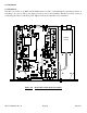
2.0 Installation 2.1 Mechanical The 2017-14 consists of one RF/Controller PCB housed in a 1 RU (1 3/4 inch high) by 16 inch deep chassis. A switching, ± 12, +24, +5 VDC power supply provides power for the assemblies. The 2017-14 can be secured to a rack using the 4 holes on the front panel. Figure 2.0 shows how the 2017-14 is assembled. POWER SUPPLY Figure 2.0 2017-14 Manual, Rev.
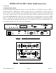
2.2 Rear Panel Input/Output Signals and Control Figure 2.2 shows the input and output connectors on the rear panel. J2 - RF IN 1.2- to 1.4 GHz input, -50 to -30 dBm, N-Type See Table 2.2. AC1 - POWER IN AC input for switching power supply. 100-240 ±10% VAC, 47-63 Hz. AC J1 - IF OUT 0.2 to 0.4 GHz, UHF Output See Table 2.2. J10 - MONITOR AND CONTROL DB9 female connector. See Table 2.1.
Tables 2.1 & 2.2 shows the input and output connectors on the rear panel. TABLE 2.1 J10 J10 Pinouts (RS-232C/422/485*) Pin Function 1 Rx- 2 Rx+ (RS-232C) 3 Tx+ (RS-232C) 4 Tx- 5 GND 6 Alarm Relay: Common 7 Alarm Relay: Normally Open 8 Not Used 9 Alarm Relay: Normally Closed *Remote Serial Interface Interface: DB-9 Male -- Protocol: RS-232C (RS-232C/422/485 option -Q), 9600 baud rate, no parity, 8 data bits, 1 start bit, 1 stop bit. TABLE 2.
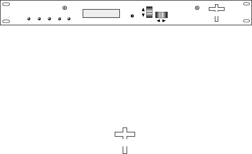
2.3 Front Panel Controls and Indicators The following are the front panel controls and indicators. DS3 - DOWN ALARM LED Red LED indicates downconverter alarm. DS1 - REMOTE LED Yellow LED indicates remote operation. LCD DISPLAY Display shows Up and Downconverter Gain in dB. S1 - MENU/EXECUTE BUTTON Press this to get into Program mode and to execute any changes. RF MONITOR UPCONV DOWNCONVERTER UPCONVERTER U U>L G = 10.0 D L>U G = 25.
2.4 Installation / Operation 2.4.1 Installing and Operating the 2017-14, Upconverter Section 1.) Connect a -40 dBm to -25 dBm signal to IF In, J4 (Figure 2.1). 2.) Connect the RF OUT, J5, to the external equipment. 3.) Connect 100-240 ±10% VAC, 47 - 63 Hz to AC on the back panel. 4.) Be sure DS6 (green, DC Power) is on and DS2 (red, Alarm) is off (Figure 2.2). 2.4.2 Installing and Operating the 2017-14, Downconverter Section 1.) Connect a -50 dBm to -30 dBm signal to RF In, J2 (Figure 2.1). 2.
Once the external 10 MHz reference is restored (on J13), the user must again manually (via the front panel LCD or Remote M&C) reselect External Reference Mode for the external 10 MHz reference to become the ‘primary’ source. L-band units with option E also have the ability to ‘insert’ the (internal or external) 10 MHz signal that has been buffered (as described above) on the center pin of the L-band (RF) connector(s). Option E1 Units with option E1 operate as described above but also have an Auto mode.
2.5 Menu Settings 2.5.1 Functions - This section describes operation of the front panel controls. There are three operator switches, the LCD display and alarm indicator LEDs. All functions for the equipment are controlled by these components. The functions are (See Figure 2.
2.5.2 Power-On Settings NOTE: THE LAST STATUS OF A UNIT IS RETAINED EVEN WHEN POWER IS REMOVED. WHEN POWER IS RESTORED, THE UNIT WILL RETURN TO IT'S PREVIOUS SETTINGS. When power is first applied, the LCD display goes through three steps. 1. The IP address is displayed 2. The software version and model number will be displayed. 192.168.123.002 2017-14 REV. 5.00 3. The present frequency and gain of the up and Downconverter is shown. U U> L G=+10.0 D L> U G=25.
2.5.4 Gain Changes When you get to this menu note that the gain changes will be made as you make them but if you do not wish to save the changes you have made, scroll to “R” and push the menu/Execute switch and select “NO” in the “SAVE SETTINGS?” window or do not press the Menu/Execute switch; simply do nothing for approximately 12 seconds, and the system will return to the normal operating mode. 2.5.4.
2.5.4.2 Downconverter Gain To set the Downconverter gain, first push the Menu/Execute switch to get to the gain setting: Operate the Menu/Execute switch until you get to the menu item you want to change see Figure 2.4 for the sequence of menu options. The following display is for changing the Downconverter gain. This is an important setting to optimize spurious and should be made as accurately as possible to provide an output in the -20 to 0 dBm level range: DN G = +30.
ON POWER UP REV 1.00 Power Up NORMAL DISPLAY Normal Display U U > L G = 10.0 D L > U G = 25.0 INT PUSH BUTTON PUSHING MENU/EXECUTE SEQUENCE R UP G = 30.0 Menu 1 Up Gain (+30 to 0) SCROLL <> SCROLL Menu 2 Down Gain (set +20 to 0) DN G = 20.
CROSS TECHNOLOGIES, INC. 6170 Shiloh Road Alpharetta, Georgia 30005 (770) 886-8005 FAX (770) 886-7964 Toll Free 888-900-5588 WEB www.crosstechnologies.com E-MAIL info@crosstechnologies.com PRINTED IN USA 2017-14 Manual, Rev.