MPR/ MIB User’s Manual Rev.
© 2002-2004 Crossbow Technology, Inc. All rights reserved. Information in this document is subject to change without notice. Crossbow is a registered trademark. DMU is a trademark of Crossbow Technology, Inc. Other product and trade names are trademarks or registered trademarks of their respective holders.
MPR/MIB User’s Manual Wireless Sensor Networks Table of Contents 1 Introduction ......................................................................................................................3 2 MPR2400 (MICAz) ..........................................................................................................4 3 4 5 2.1 Product Summary.................................................................................................. 4 2.
MPR/MIB User’s Manual Wireless Sensor Networks 12.1 Programming the Mote ........................................................................................ 36 12.2 RS-232 Interface ................................................................................................. 36 13 MIB510 Serial Interface Boards ...................................................................................37 13.1 Product Summary.................................................................................
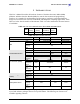
MPR/MIB User’s Manual Wireless Sensor Networks 1 INTRODUCTION This User’s Manual describes the hardware features of the Mote Processor Radio (MPR) platforms and Mote Interface Boards (MIB) for network base stations and programming interfaces. It is intended for understanding and leveraging Crossbow’s Smart Dust hardware design in real-world sensor network, smart RFID, and ubiquitous computing applications. Table Table 1-1 below lists the models in this Manual.
MPR/MIB User’s Manual Wireless Sensor Networks q TinyOS Getting Started Guide by Crossbow Technology, Inc. available on the TinyOS Support Tools CDROM or the Crossbow web site at www.xbow.com under Support>User’s Manuals. q The TinyOS web site at http://webs.cs.berkeley.edu/tos Doc. # 7430-0021-06 Rev.
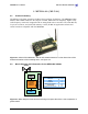
MPR/MIB User’s Manual Wireless Sensor Networks 2 MPR2400 (MICAZ ) 2.1 Product Summary The MICAz is the latest generation of Motes from Crossbow Technology. The MPR2400 (2400 MHz to 2483.5 MHz band ) uses the Chipcon CC2420, IEEE 802.15.4 compliant, ZigBee ready radio frequency transceiver integrated with an Atmega128L micro-controller. The same MICA2, 51 pin I/O connector, and serial flash memory is used; all MICA2 application software and sensor boards are compatible with the MPR2400. Figure 2-1.
MPR/MIB User’s Manual 2.2.1 Wireless Sensor Networks 51-pin Expansion Connector Doc. # 7430-0021-06 Rev.
MPR/MIB User’s Manual 2.2.2 Wireless Sensor Networks CC2420 Radio Doc. # 7430-0021-06 Rev.
MPR/MIB User’s Manual 2.2.3 Wireless Sensor Networks Battery, ADC1 Doc. # 7430-0021-06 Rev.
MPR/MIB User’s Manual 2.3 Wireless Sensor Networks FCC Certification for the MICAz The MICAz Mote is classified by the FCC as both a Class A and a Class B digital device. As such this section describes how to operate the equipment so that it does not cause unintended RF interference. 2.3.1 Class A & B Digital Device Compliance This equipment has been tested by the FCC and found to comply with the limits for a Class A digital device, pursuant to Part 15 of the FCC Rules.
MPR/MIB User’s Manual Wireless Sensor Networks 3 MPR400/MPR410/MPR420 (MICA2) 3.1 Product Summary The MICA2 Motes come in three models according to their RF frequency band: the MPR400 (915 MHz), MPR410 (433 MHz), and MPR420 (315 MHz). The Motes use the Chipcon CC1000, FSK modulated radio. All models utilize a powerful Atmega128L micro-controller and a frequency tunable radio with extended range. The MPR4x0 and MPR5x0 radios are compatible and can communicate with each other.
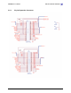
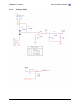
MPR/MIB User’s Manual 3.2.1 Wireless Sensor Networks Battery, Power, and ADC1 R6 ADC7 TP3 10K BT1 V+ V- 1 BAT_MON 3 18.2K 2 2 1 U2 R7 BATTERY_2AA LM4041-1.2 VCC R2 R1 D1 0 OHM BAT54C 0 OHM 1 SW2 VSNSR R3 2 3 R4 0 OHM SPDT 0 OHM R5 1K J4 C2 .1uF C1 .1uF 1 1 2 2 CONN VSNSR R8 BOARD OPTIONS ADC[0..7] ADC1 R1 R2 R4 R8 RT1 INSTALL NOT INSTALLED NOT INSTALLED NOT INSTALLED NOT INSTALLED 10K RT1 10.0K THERM_PWR 3.2.
MPR/MIB User’s Manual 3.2.3 Wireless Sensor Networks 51-pin Expansion Connector: Location J21 PW[0..7] PIN UART_RXD0 UART_TXD0 VSNSR J21 BAT_MON LED3 LED2 LED1 RD WR ALE PW7 USART1_CLK PROG_MOSI PROG_MISO SPI_SCK USART1_RXD USART1_TXD I2C_CLK I2C_DATA PWM0 PWM1A AC+ AC- 1 2 3 4 5 6 7 8 9 10 11 12 13 14 15 16 17 18 19 20 21 22 23 24 25 26 PLUG INT3 INT2 INT1 INT0 HIROSE INT[0..
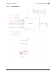
MPR/MIB User’s Manual 3.2.5 Wireless Sensor Networks ATMega128L VSNSR VCC R15 C21 470 C22 .1uF R16 10K C23 .1uF RSTN 64 62 20 .
MPR/MIB User’s Manual 3.2.6 Wireless Sensor Networks Flash Memory, Serial ID, LEDs, USART VCC + C24 10uF 10V C25 .01uF C26 .01uF C27 .01uF C28 .01uF C29 .01uF C30 .01uF VCC VCC R19 USART1_RXD C31 1000pF C32 1000pF C33 1000pF C34 1000pF R22 1M UART_TXD0 1M R23 FLASH_CS VCC USART1_TXD USART1_CLK FLASH_CS U5 1 2 3 4 4.
MPR/MIB User’s Manual Wireless Sensor Networks 4 MPR500/MPR510/MPR520 (MICA2DOT) 4.1 Product Summary The MICA2DOT is a Mote designed for applications where physical size is important. Like the MICA2, these are available in three models according to the frequency of the RF transceiver: the MPR500 (915 MHz), MPR510 (433 MHz), and MPR520 (315 MHz). The Motes use the Chipcon CC1000 FSK-modulated radio.
MPR/MIB User’s Manual Wireless Sensor Networks b = 0.000214381 c = 0.000000093 R1 = 10 k? ADC_FS = 1023 ADC = output value from the Mote’s ADC measurement. 4.3 Block Diagram and Schematics for the MPR500/510/520 MICA2DOT Antenna 19 peripheral pins Logger Flash ATMega128L µcontroller Analog I/O Digital I/O Freq. Tunable Radio Feature Battery / Ext. Power Radio Antenna Data Flash Logger Atmega128 Expansion Connector Chapter 6 7 8 9 10 11 25 mm Figure 4-1.
MPR/MIB User’s Manual 4.3.1 Wireless Sensor Networks MICA2DOT CC1000 Radio Side L3 C10 AVCC SPI_SCK VCCA AVCC 23 24 25 26 27 DCLK PCLK PDATA PALE 10 11 13 L8 DIO DCLK PCLK PDATA PALE 21 C12 VCC SPI_MISO AVCC AVCC AVCC AVCC U3 CC1000 1 5 9 15 R13 10K RF_IN RF_OUT CHP_OUT RSSI L1 L2 R_BIAS XOSC1 XOSC2 L4 3 C13 4 12 28 POT_PWR 18 17 TP17 R18 82.5K C16 .001uF C17 4.7pF R17 27.4K TP18 L9 ADC0 R35 10K C18 C19 Y1 1 X1 X2 2 14.
MPR/MIB User’s Manual 4.3.2 Wireless Sensor Networks MIC2DOT ATMega128L, ADC Interfaces, Battery VCCA C22 R21 .1uF 470 R22 C23 10K VCCA .
MPR/MIB User’s Manual 4.3.3 Wireless Sensor Networks Data Flash Logger/Serial ID, On-board Thermistor, LED VCCA R36 ADC1 VCCA 10K D5 RT1 10.0K + SD103AW C24 10uF 10V C25 .01uF C26 .01uF PW7 PW6 VCCA VCCA R26 FLASH_SO 1M R29 C31 1000pF UART_TXD0 R30 C32 1000pF 1M SERIAL_ID 4.7K VCCA D2 LED1 2 R31 1 470 RED SERIAL_ID U7 1 2 3 4 SI SCK RST CS GNDVCC VCCA FLASH_SI FLASH_CLK 6 VCCA SO WP 8 FLASH_SO 5 R25 100K 7 AT45DB041 RSTN Doc. # 7430-0021-06 Rev.
MPR/MIB User’s Manual Wireless Sensor Networks 5 MPR300/MPR310 (MICA) X NOTE: The MICA Mote has been discontinued by Crossbow since December 2003. The MICA Mote was the second generation Mote module used in many ground breaking research and development efforts. The MPR300/310 includes a powerful Atmel ATMega128L. It used an amplitude shift keying radio—the TR1000—by RF Monolithics, Inc. 5.1 Schematic Schematics for the MPR300/410 Mote can be found at: http://today.cs.berkeley.edu/tos/hardware/hardware.
MPR/MIB User’s Manual Wireless Sensor Networks 6 POWER 6.1 Battery Power All motes are designed for battery power. The MICA2 and MICAz form factors are designed to match up with two AA batteries; however any battery combination (AAA, C, D, etc., cells) can be used provided that the output is between 2.7 VDC to 3.6 VDC.
MPR/MIB User’s Manual Wireless Sensor Networks Table 6-3. Estimate of battery life operation for a Mote. SYSTEM SPECIFICATIONS Example Duty Cycle Currents Processor Current (full operation) Current sleep 8 mA 8 µA 1 99 Radio Current in receive 8 mA Current transmit 12 mA Current sleep 2 µA 0.75 0.
MPR/MIB User’s Manual Wireless Sensor Networks Figure 6-4. Photo of using the Molex connector to attach the AA battery pack. Photo courtesy of Nick Sitar, UC Berkeley, 2004. 6.3 MICAz Battery Voltage Monitor The MICAz has an accurate internal voltage reference that can be used to measure battery voltage (Vbatt). Since the eight-channel ADC on the ATMega128L uses the battery voltage as a full scale reference, the ADC full scale voltage value changes as the battery voltage changes.
MPR/MIB User’s Manual Wireless Sensor Networks To compute the battery voltage: 1. Set the BAT_MON processor pin (PA5/AD5) to HI. 2. Program the application code to measure ADC Channel 7. 3. Compute battery voltage, Vbatt, from Channel 7’s data by: Vbatt = Vref × ADC _ FS ADC _ Count where: Vbatt = Battery voltage ADC_FS = 1024 Vref = External voltage reference = 1.223 V ADC_Count = Data from the ADC measurement of Channel 7 6.
MPR/MIB User’s Manual Wireless Sensor Networks 7 RADIOS 7.1 7.1.1 MICA2 and MICA2DOT Radio Considerations The radio on the MICA2 and MICA2DOT is capable of multiple channel operation, within the intended band of operation. The MPR420/MPR520 can span up to 4 channels of operation in the 315 MHz band, the MPR410/MPR510 can span up to 4 channels of operation in the 433 MHz band (433.05–434.79 MHz).
MPR/MIB User’s Manual Wireless Sensor Networks Table 7-1. Chipcon® CC1000 Ouput Power (PA_POW) Settings and Typical Current Consumption. From Smart RF® CC1000 Preliminary Datasheet (rev. 2.1), 2002-04-19, p. 29 of 48. Pout (dBm) PA_POW (hex) 433/315 MHz Current Consumption, typ. (mA) PA_POW (hex) 915 MHz Current Consumption, typ.
MPR/MIB User’s Manual Wireless Sensor Networks VRSSI = Vbatt × ADC _ Counts 1024 RSSI (dBm ) = −51 .3 × V RSSI − 49 .2 for 433 and 315 MHz Motes RSSI (dBm ) = −50. 0 × VRSSI − 45 .5 for 915 MHz Motes Figure 7-2. Graph showing V RSSI versus the received signal strength indicator (dBm). From the ChipCon’s SmartRF® CC1000 PRELIMINARY Datasheet (rev. 2.1), p. 30. 2002. Care should be taken to provide an antenna that provides proper coverage for the environment expected.
MPR/MIB User’s Manual Wireless Sensor Networks Power Register (code) MICAz TX RF Power (dBm) 31 27 23 19 15 11 7 3 0 -1 -3 -5 -7 -10 -15 -25 The RF received signal strength indication (RSSI) is read directly from the CC2420 Radio. In TinyOS the RSSI is automatically returned in the TOSMsg->strength field with every radio packet received. Typical RSSI values for a given RF input level are shown in Figure 7-1 below. Figure 7-2. Typical RSSI value versus input RF level in dBm. 7.2.
MPR/MIB User’s Manual Wireless Sensor Networks X NOTE: Programmers should be cautioned that the MICAz receiver radio stack (CC2420RadioM.nc) will be disabled if the INT2 pin is reprogrammed/re-tasked by another TOS component. 4. MTS300/310 (a.k.a., micasb) Temperature Sensor • • INT2 control line is used on the MTS300/310 (micasb) for enabling the thermistor. During temperature measurement, interrupts from the MICAz radio receiver are inhibited.
MPR/MIB User’s Manual Wireless Sensor Networks 8 ANTENNAS 8.1 Radio/Antenna Considerations Care should be taken to provide an antenna that provides proper coverage for the environment expected. Range and performance are strongly affected by choice of antenna and antenna placement within the environment. In addition, care must be taken to ensure compliance with FCC article 15 regulations for intentional radiators.
MPR/MIB User’s Manual Wireless Sensor Networks Right Angle RG178/U H3221-ND MMCX-LP-178B/U Right Angle RG316/U H3222-ND MMCX-LP-316/U Doc. # 7430-0021-06 Rev.
MPR/MIB User’s Manual Wireless Sensor Networks 9 FLASH DATA LOGGER AND SERIAL ID C HIP All Motes feature a 4-Mbit serial flash (Atmel AT45DB041) for storing data, measurements, and other user-defined information. It is connected to one of the USART on the ATMega128L. This chip is supported in TinyOS which uses this chip as micro file system. The serial flash device supports over 100,000 measurement readings. This chip is also used for over-the-air reprogramming services available in TinyOS.
MPR/MIB User’s Manual Wireless Sensor Networks 10 ATMEGA128 F USES The ATMega128L processor on the Motes has many programmable fuses to control various parameters. Refer to Atmel’s technical information for the ATMega128L for a complete discussion of the fuses (http://www.atmel.com/dyn/resources/prod_documents/2467s.pdf). There are two fuses that TinyOS users should be aware of as setting these fuses incorrectly will cause the unit to not operate correctly. 10.1.
MPR/MIB User’s Manual Wireless Sensor Networks 11 SENSOR BOARDS & EXPANSION C ONNECTORS Crossbow supplies a variety of sensor and data acquisition boards for the Motes. This Chapter describes the connectors and the functions of the pins for the MICAz, MICA2, MICA, and MICA2DOT. Information for customized sensor board design is available on the Crossbow web site. 11.1 Sensor Board Compatibility Table 11-1. Sensor board compatibility.
MPR/MIB User’s Manual 11.2.1 Wireless Sensor Networks MICAz and MICA2 Sensor Interface. Table 11-2. MICAz Sensor Interface.
MPR/MIB User’s Manual 11.3 Wireless Sensor Networks MICA2DOT Expansion Connector The interface to the MPR500 is through a series of 19 pins Elpacko spaced around the circumference of the MPR5x0 Mote. (They represent a subset of the pins available on the MPR5x0.) They include a set of power control pins, ADC channels, power, ground, some general purpose digital IO, and the serial programming port.
MPR/MIB User’s Manual Wireless Sensor Networks 12 MIB300 / MIB500 INTERFACE B OARDS X NOTE: The MIB300 and MIB500 have been discontinued by Crossbow. The MIB500 has been replaced by the MIB510. M WARNING: When programming a MICA2 with the MIB500, turn off the battery switch. For a MICA2DOT, remove the battery before inserting into the MIB500. The MICA2s and MICA2DOTs do not have switching diodes to switch between external and battery power. 12.
MPR/MIB User’s Manual Wireless Sensor Networks 13 MIB510 SERIAL INTERFACE B OARDS X NOTE: The MIB510 will only work with ATMega128 processors used on the MICA2 and MICA2DOT. It will work for older Mica units that have the ATMega128 processor but not earlier processors such as the ATMega103. 13.1 Product Summary The MIB510 interface board is a multi-purpose interface board used with the MICAz, MICA2, MICA, and MICA2DOT family of products. The board is supplied with all MOTE-KITs.
MPR/MIB User’s Manual Wireless Sensor Networks depend on the Mote platform you are programming. Instructions can also be found in the Getting Started Guide. M WARNING: Under Cygwin the ISP may not get control of the serial port if the Mote is continually sending packets over the serial TX line at a high rate. If this happens, the UISP will hang. This can be fixed by: 1. Type Ctrl C in the Cygwin window and try again. 2. Turn SW2 to the “ON” position. This turns on a circuit to disable the Mote’s TX line.
MPR/MIB User’s Manual 13.4.5 Wireless Sensor Networks Schematics PW[0..7] UART_RXD0 UART_TXD0 VSNSR J2 BAT_MON LED3 LED2 LED1 RD WR ALE PW7 USART1_CLK PROG_MOSI PROG_MISO SPI_SCK USART1_RXD USART1_TXD I2C_CLK I2C_DATA PWM0 PWM1A AC+ AC- PLUG INT3 INT2 INT1 INT0 1 2 3 4 5 6 7 8 9 10 11 12 13 14 15 16 17 18 19 20 21 22 23 24 25 26 HIROSE INT[0..
MPR/MIB User’s Manual Wireless Sensor Networks PIN 1 2 3 4 5 6 7 8 9 10 11 12 13 14 15 16 17 18 19 20 21 22 23 24 25 26 Doc. # 7430-0021-06 Rev.
MPR/MIB User’s Manual 13.4.6 Wireless Sensor Networks RS-232, MICA2DOT, and Ext. Power Interface. J4 TP5 13 25 12 24 11 23 10 22 9 21 8 20 7 19 6 18 5 17 4 16 3 15 2 14 1 TP6 J6 5 9 4 8 3 7 2 6 1 RS232_RX RS232_TX DB9 -F-R A VCC J5 LPT1_MISO 1 2 3 4 5 6 7 8 9 10 11 12 13 14 15 16 17 18 19 LPT1_RST LPT1_MOSI LPT1_SCK ADC[0..
MPR/MIB User’s Manual Wireless Sensor Networks 14 MIB600CA 14.1 Introduction The MIB600CA provides Ethernet (10/100 Base-T) connectivity to MICA2 family Motes for communication and in-system programming. Its two standard configurations are a) an Ethernet Gateway for a Mote network and b) a Mote network programming and out-band diagnostic channel. The MIB600CA device contains, on a 4.5” × 2.
MPR/MIB User’s Manual 14.2.1 Wireless Sensor Networks Physical For other than temporary installations, the MIB600 should be installed in a ground isolated enclosure. 14.2.2 MICA Mote Connection MICAz and MICA2 Motes connect to the MIB600 directly via the standard mote 51-pin HIROSE connector at J1. Two mounting holes are provided for securing the MICA2 Mote when installed at J1.
MPR/MIB User’s Manual Wireless Sensor Networks Table 14-2. Pin Outs for a LAN Connection 14.3 14.3.1 Pin No. Strand Color Name 1 white and orange TX+ 2 orange TX- 3 white and green RX+ 4 blue 0V POE 5 White and blue 0V POE 6 green RX- 7 Brown and white -48V POE 8 Brown -48V POE Host Software UISP UISP version 20030820tinyos or newer is required. This version is included in the TinyOS 1.1.0 September 2003 release package.
MPR/MIB User’s Manual Wireless Sensor Networks Serial Server RESET. Pressing the S1 switch on the server sub- module (U15) manually resets the Ethernet serial server. XNOTE The MIB600 and attached Mote are not reset. The serial server can also be reset via Telnet at Port 9999. ISP LED. During in-system programming of a Mote the ISP LED (D3) is ON. Mote LEDs. Three LEDs (red, green, yellow) correspond to the attached Mote’s indicators. 14.4.
MPR/MIB User’s Manual Wireless Sensor Networks Table 14-6. Controls, Indicators, and Connector Summary. ID NAME DESCRIPTION CONTROLS SW1 SW2 RESET MIB600 Manual RESET pushbutton. Resets MIB600 ISP controller and attached MOTE. POWER SELECT 5V POE Serial Server Reset Selects External 5VDC power source at J7 Selects Power Over Ethernet provided at RJ45/J10 Reset Serial Server.
MPR/MIB User’s Manual Wireless Sensor Networks 15 APPENDIX A: 10/100 B ASE-T C ABLING Category 5(e) (UTP) color coding table Doc. # 7430-0021-06 Rev.
MPR/MIB User’s Manual Wireless Sensor Networks 16 WARRANTY AND SUPPORT INFORMATION 16.1 Customer Service As a Crossbow Technology customer you have access to product support services, which include: q Single-point return service q Web-based support service q Same day troubleshooting assistance q Worldwide Crossbow representation q Onsite and factory training available q Preventative maintenance and repair programs q Installation assistance available 16.
MPR/MIB User’s Manual 16.3.3 Wireless Sensor Networks Identification and Protection If the equipment is to be shipped to Crossbow for service or repair, please attach a tag TO THE EQUIPMENT, as well as the shipping container(s), identifying the owner. Also indicate the service or repair required, the problems encountered, and other information considered valuable to the service facility such as the list of information provided to request the RMA number.
Crossbow Technology, Inc. 41 Daggett Drive San Jose, CA 95134 Phone: +1 408 965 3300 Fax: +1 408 324 4840 Email: info@xbow.