
Installation Manual
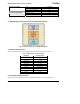
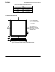
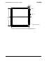
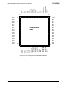
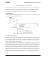

Table Of Contents
- About This Document
- 1 Introduction
- 2 Quick Start for the OEM Kit Users
- 3 Product Overview
- 4 IRIS OEM Reference Board
- 5 Power
- 6 Radios
- 7 Antennas
- 8 Flash Data Logger and Serial ID Chip
- 9 Atmega1281 Fuses
- 10 Sensor Boards & Expansion Connectors
- 11 USB Programming Pod
- 12 Appendix A. Warranty and Support Information

IRIS OEM Edition Hardware Reference Manual
The RF output port is 50 ohm and can be connected directly to a 50 ohm microstrip or 50 ohm
coaxial cable. A PI-Matching network is recommended for antenna matching especially when
using inner antennas. If the antenna’s input impedance is not 50 ohm, please contact antenna
vendor and ask for matching network value.
An example of a typical layout is shown in Figure 4-2.
OEM Module
OEM Module
Figure 4-2. An example layout for OEM Edition Module
4.3 Circuit Design Considerations
An external crystal is not required. The unit can be configured to run on the internal RC
oscillator, leaving the crystal connections open. If an external crystal is to be used, place the
crystal as close to the input pins as possible to reduce parasitics. When selecting capacitors for
the crystal, take into account the stray capacitance from the board to the module and adjust
accordingly. If an external clock is used, XTL1 (PIN 6) should be used, and XTL2 (PIN 5)
should be left open. For proper operation, correct selection of clock fuse options is required.
XTAL1 and XTAL2 are input and output, respectively, of an inverting amplifier which can be
configured for use as an On-chip Oscillator, as shown in Figure 4-3. Either a quartz crystal or a
ceramic resonator may be used. Normally, a 7.3728 MHz crystal is used for units requiring serial
communication. The CKOPT fuse selects between two different Oscillator Amplifier modes.
Doc. # 7430-0549-01 Rev. B Page 15