
Installation Manual
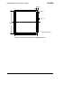
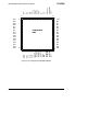

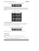
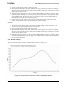
Table Of Contents
- About This Document
- 1 Introduction
- 2 Quick Start for the OEM Kit Users
- 3 Product Overview
- 4 IRIS OEM Reference Board
- 5 Power
- 6 Radios
- 7 Antennas
- 8 Flash Data Logger and Serial ID Chip
- 9 Atmega1281 Fuses
- 10 Sensor Boards & Expansion Connectors
- 11 USB Programming Pod
- 12 Appendix A. Warranty and Support Information

IRIS OEM Edition Hardware Reference Manual
2) Apply a small amount of flux to the tinned pads.
3)
Place the OEM module on the pads, making sure to have the pin one reference markings
aligned. Inspect the placement to make sure the OEM module edge contacts are centered
on the pads on all four sides.
4)
While applying mild pressure to the top of the OEM module (to hold it in position), apply
heat from a fine soldering tip to the area of the pre-tinned pad that is exposed at the edge
of the OEM module. Reflow only one corner pad first, and verify the OEM module is
still positioned correctly on the remaining pads.
5)
Using a fine solder tip, reflow each of the pre-tinned pads until the solder flows and
makes contact with the pad on the underside of the OEM module.
Method 2:
1)
Pre-tin the surface mount pads on the board the OEM module will be soldered to. Be
careful to use an equal amount of solder on each pad.
2)
Apply a small amount of flux to the tinned pads.
3)
Place the OEM module on the pads, making sure to have the pin one reference markings
aligned. Inspect the placement to make sure the OEM module edge contacts are centered
on the pads on all four sides.
4)
While applying mild pressure to the top of the OEM module (to hold it in position), apply
heat from a thermal heat gun to the edges of the OEM module until the exposed solder on
the pre-tinned pads melts.
4.4.2 Machine Soldering
The recommended solder profile for OEM module is shown in Figure 4-4.
Figure 4-4. Recommended Temperature Profile for OEM Edition Module
Page 18 Doc. # 7430-0549-01 Rev. B