82092 Issue 4 7+( 785%2 72$67(5 0.
Description The Turbo-Toaster Mklll is a decorative gas fire that has been designed for use in applications that do not have a conventional chimney or flue but where an appliance can be located so as the flue can terminate on an outside wall. The flue has a built-in canopy with a horizontal flue duct running through the wall terminating with a fan housing box attached to the exterior wall. A control box is positioned on the right hand side of the appliance behind the front and fret.
Additional purpose built ventilation is not required far this appliance in GB only, for IE ventilation is required with a minimal cross sectional area of 100sq.cms. and it should be checked regularly to ensure that it is free from obstruction. The chimney or flue must be swept before installation (unless new).
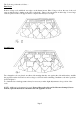
IMPORTANT: After turning OFF, or if the pilot and appliance go out for any other reason, wait for 3 minutes before attempting to relight. NOTE: The appliance is fitted with an Oxy-pilot to prevent the continued operation in the event of spillage occurring. If the fire shuts ’off’ repeatedly the appliance must be turned off and not used until an expert is consulted. Relaying the coal bed after cleaning (see Figs.
The Coals are positioned as follows: First Layer Position 4 large coals with their rear edges on the burner inserts. Place 3 large coals at the rear of the coal support shelf and lay 2 further at the sides of the shelf. These coals are placed on their edge. 3 more large coals are placed on the coal support shelf to complete the first layer. See fig 2.
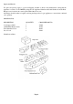
Spares and Service For spares and service, apply to your local Supplier, installer or direct to the manufacturer, stating that the appliance is a Turbo Toaster MKIII quoting the GC Appliance Number and Serial Number from the Data Badge located on the front controls panel behind the front cover. Advantage should be taken of regular servicing and inspection for gas appliances to ensure their continued safe operation. Short Parts List DESCRIPTION QUANTITY CROSSLEE PART No.
Registration Record Purchasers Name ....................................................................................................... and Address ....................................................................................................... .................................................................................................................................... Supplier’s Name .......................................................................................................
2091 Issue 5 Dec/1998 7+( 785%2 72$67(5 0.
Description The Turbo-Toaster Mklll is a decorative gas fire which incorporates a horizontal flue that has been designed for use in applications that do not have a conventional chimney or flue but where an appliance can be located so as the flue can terminate on an outside wall. The maximum wall thickness is 600mm and the minimum thickness 100mm. The flue must be straight and no bends or elbows are permitted.
Maximum heat input (GROSS) Minimum heat input (GROSS) Inlet pressure Injector Gas Valve Solenoid Valve Maximum wall thickness Minimum wall thickness Electrical supply 6.6kW (22520Btu/h) 4.
Flue Terminal Positions TERMINAL POSITION MINIMUM DISTANCE A - Directly below an openable window or other opening e.g. air-brick B - Below gutters, soil pipes or drain pipes C - Below eaves D - Below balconies or car port roof E - From vertical drain pipes and soil pipes F - From internal or external corners G - Above ground, roof or balcony level H - From a surface facing a terminal I - From a terminal facing a terminal J - From an opening in the car port (e.g.
Dimension A: The distance from the surface of any part of the appliance to any combustible material is either a minimum of 75mm air gap or 25mm of insulated material. Check List of Components Hotbox C/W gather and burner assembly Flue duct Aluminium Conduit Fan Box Assembly Flue Mounting Plate Ceramic Fibre Gasket Closure Plate Users Instructions Installation & Servicing Instructions Front &: Fret 8mm Formed Bundy 43mm x 8mm.
Installing the Appliance To install the appliance it is necessary to have a gas supply and an electrical supply close to the proposed siting of the appliance. If the BE MODERN HARMONY surround and hearth is being used it is advisable that the services are laid as shown in Fig.3. In all applications the appliance must be fixed in position at the top at the gather by the two tabs provided and at either of the additional fixing positions provided in the base or through the rear panel of the hot box.
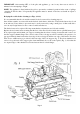
It is advisable to remove the burner assembly from the box to prevent any unnecessary damage being caused and to ease the handling of the fire.
To Dismantle the Appliance Prior to Installation Remove the two screws securing the burner in position, (See Fig. 4) carefully pull the burner forward (taking care to avoid placing any stress an the wires supplying power to the solenoid valve. Fig.7). Disconnect the cable at the small plug and socket by lifting the small locking lever. This will give access to the heat shield covering the control box and wiring connections.
The minimum thickness of insulation beneath the appliance for combustible floors is 18mm, therefore if: (a) The floor is a solid non-combustible floor - a minimum hearth thickness of l2mm with the perimeter of 50mm is required. Refer to Fig. 6. (b) The floor is a timber or suspended floor - a minimum thickness of 18mm is required with a perimeter of 50mm. See B on Fig. 6. If a suspended timber floor is being used check that the joists are capable of supporting any structure that may be used.
Where the appliance is to be installed against a wall, a Rockwool gasket is provided to slide over the flue before the appliance is placed in position. The function of this is to form a seal between the rear of the appliance and the cavity between the inner and outer walls of a cavity wall construction. See Fig. 8.
On the surround backpanel if a minimal total depth of the installation is required, see Fig. 11. The spacer strips supplied can be used to increase the depth where it is necessary to leave a space between the wall and the rear of the appliance. If a surround is being used it is not necessary for the chimneybreast to enclose the appliance thereby allowing a larger gap between any combustible materials and the appliance. The surround should be installed in accordance with the manufacturer’s instructions.
This type of installation can normally be used with non-combustible cavity wall constructions, and allows a greater choice of surrounds and fireplaces to be used where space is of the greater importance. Where the inner leaf of a non-combustible wall is to be removed i.e. block or brickwork, the opening should be made the same size as indicated in Fig. 12 and a support or lintel inserted over the opening. Care must be taken to ensure that any combustible material in the cavity (polystyrene foam etc.
The appliance can be installed as in A2 and sealed around the sides, top and the cavity with Rockwool to prevent any combustible material falling onto the surfaces or the rear of the hot box and flue duct. The cavity must also be sealed around the sides and top of the hot box with a non-combustible materia1 or insulated board as shown in Fig. 14. A suitable hearth and surround must be fitted or constructed.
The heatshield supplied in the timber frame kit is manufactured in two pieces, an inner and outer skin with approx. 25mm air gap between. Measure the total thickness of the inner wall, the heatshield must be trimmed down to the depth of the inner wall and should not project more than 10mm into the cavity. Remove the two screws securing the two skins together which will then enable the two halves to be trimmed with a pair of tinsnips or hacksaw, replace the two halves and screw together.
Assembly of the Fan Box to the Exterior Wall With the flue attached to the rear of the fire and located in the correct position the flue and the wiring harness will be protruding from the wall. Providing the fire will not have to be removed for any further structural work to be carried out the fan box can be fixed into position and the electrical connection made. In most installations the flue tube will need to be trimmed to the correct length.
As previously stated a length of cord or wire should be taped or tied to the loom, feed through the conduit supplied (the flanged end is positioned nearest to the fan), keeping the loom taut slide the conduit through the mounting plate. Locate over the extruded hole at the rear of the gather and measure the distance to be trimmed i.e. between the mounting plate and the underside of the flanged conduit.
To connect the gas supply TURN OFF ANY OTHER APPLIANCES THAT ARE FED BY THE METER ISOLATE THE GAS SUPPLY AT THE METER Complete the connection from the gas supply to the isolation cock/restrictor elbow; replace the control box heat shield - if it has been removed. Replace the burner assembly, connect the solenoid supply cable and plug to the socket, position the burner assembly so as the two feet of the rear legs locate under the two tags In the base of the fire.
First Layer Position 4 large coals with their rear edges on the burner inserts. Place 3 large coals at the rear of the coal support shelf and lay 2 further at the sides of the shelf. These coals are placed on their edge. 3 more large coals are placed on the coal support shelf to complete the first layer. See fig 19. Second Layer Two triangular coals are placed one either side ensuring that they rest against the side and that they straddle the gap between the front and second row large coal.
Check the Operation of the Electrical Circuit Complete any connections not already made at the exterior fan box. With power connected to the appliance, push the left hand (on) button, a click will be heard which is the operation of the gas solenoid and the red neon will show for a short period until sufficient flue flow has been established. In very cold conditions the neon may cycle a few times before stabilising, this is normal and is because of the viscosity of the grease in the fan bearings.
Check for satisfactory clearance of combustion products. Light the appliance and set to maximum input, locate the front and fret in position and leave to warm up for 5 minutes. Check for satisfactory clearance of combustion products by positioning a lighted smoke match in the centre of the fire opening, 200mm below the canopy and level with the rear edge of the simulated front coal, see Fig. 21. All the smoke must be drawn into the flue, if spillage occurs, allow a further 10 minutes.
SERVICING It is recommended that the appliance is inspected and serviced as necessary regularly by a competent person e.g. Manufacturer’s Distributor’s representatives, Corgi installer. The life of the ceramic coals and fire back will be dependent on the way they are handled/knocked/ dropped/used. Any damaged or disintegrating coals should be replaced. IMPORTANT NOTE: The specific number of coals should not be exceeded. The fan should be dismantled from the fan box and the blades etc.
3. TO REPLACE THE IGNITER LEAD • • • Withdraw the burner assembly as detailed in 2.1 to 27 Unplug the igniter lead from the electrode and piezo igniter. Replace igniter lead. Reassemble all components in reverse order of removal, check spark and ignition. 4.
7. TO REPLACE THE GAS CONTROL (TAP/FSD) • • • • • Withdraw the burner assembly as detailed in 2.1 to 2.7. Disconnect the three gas pipes and the thermocouple from the control. Pull off the knob and lay to one side. Undo the retaining nut at the front of the tap niting assembly to withdraw control from the mounting bracket. Replace in reverse order of removal. Check for gas soundness. 8. TO REPLACE THE PIEZO IGNITER • • • Withdraw the burner assembly as detailed in 2.1 to 2.7.
12. TO SERVICE THE FAN MOTOR • • • • • Disconnect the electrical supply. Remove the terminal guard if fitted, fan box cover and deflector plate as detailed in 11.1 to 11.3. Disconnect the electrical connections to the fan at the terminal block and earth post noting their positions. Unscrew the three hex headed screws on the perimeter of the fan motor assembly mounting plate and withdraw the fan and impeller assembly leaving the fan scroll in situ. Clean any soot or lint from the fan impeller and casing.
13. TO REPLACE THE SOLENOID VALVE OR SOLENOID COIL • • Withdraw the burner assembly as detailed in 21 to 2.7. To remove the complete valve unscrew the screw in the centre of the plug sufficient to allow the plug to be removed from the solenoid coil. Disconnect the two compression nuts holding the valve in position remove the two fittings from the valve body and clean any old thread sealant from the fittings.
FAULT SYMPTOMS POSSIBLE CAUSES ACTION Lamp not illuminating if on switch is operated Fan not running Blown fuse Check supply fuse and ascertain cause of blowing and replace fuse. Replace pressure switch. Lamp remains illuminated Pressure switch not returning to the (NC) position.
DESCRIPTION CROSSLEE PART No G.C.
Registration Record Purchasers Name ....................................................................................................... and Address ....................................................................................................... .................................................................................................................................... Supplier’s Name .......................................................................................................