
User manual


Maximum heat input (GROSS) 6.6kW (22520Btu/h)
Minimum heat input (GROSS) 4.12kW (14060 Btu/h)
Inlet pressure 20 mbar (8 in wg)
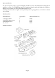
Injector Stereomatic type 046/19/196/79
Gas Valve Isphording GH379-001-003-00A or Thermoco 21300B
Solenoid Valve Johnson Controls SM302-0500-VQ01
Maximum wall thickness 600mm
Minimum wall thickness 100mm
Electrical supply 220-240 v ~ 50 Hz
Ventilation
Additional purpose built ventilation is not required for this appliance in GB only, for IE ventilation is required
with a minimal cross section area of 100sq. Cms and should be checked regularly to ensure that it is free from
obstruction.
The fire must only be used with the Front and Fret supplied.
Location of Appliance
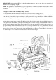
The appliance must always be fitted with a hearth having a minimum depth of 300mm from the front vertical
face of the Hotbox and a minimum width of 700mm. See Fig 2 (see later in the instructions for minimum
thickness requirements).
The location of the appliance will be determined in conjunction with the requirements of a surround or
structure that is to be used and a suitable position for the flue outlet terminal. A guide to the constraints
regarding the position of the flue outlet terminal is listed below this is an extract from BS 5440 Pt.1 1990.
General Notes
1. The terminal must be positioned such that the combustion products can disperse freely at all times.
2. In certain weather conditions a terminal may steam and positions where this could cause a nuisance should
be avoided.
3. If the terminal discharges onto a passageway or pathway or over an adjoining property check that the
terminal will not obstruct the passageway. In some areas local bylaws ask for a minimum height for
projections from a wall above a public footpath. Check any local bylaws!
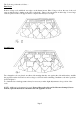
4. If the terminal is fitted within 850mm of a plastic gutter or within 450mm of painted eaves or a painted
gutter an aluminium shield at least 750mm long should be fitted to the underside of the gutter or painted
surface. (Dimensions B & C in Fig. 1)
5. If a terminal is fitted less than 2m above a balcony, above ground or above a flat roof to which people have
access then a suitable terminal guard must be provided. (Dimension G n Fig 1)
6. A terminal sited in a carport or other single storey add-on extension should be treated with care and the
additional notes in Table 2 apply. Whilst other building features may satisfy the dimensional requirements,
they are not included e.g. covered passages between dwellings
Page 3