CE Series CE 1000 Operation Manual CE 2000 Obtaining Other Language Versions: To obtain information in another language about the use of this product, please contact your local Crown Distributor. If you need assistance locating your local distributor, please contact Crown at 574-294-8000. This manual does not include all of the details of design, production, or variations of the equipment. Nor does it cover every possible situation which may arise during installation, operation or maintenance.
CE Series Power Amplifiers Important Safety Instructions 1) 2) 3) 4) 5) 6) 7) 8) 9) 10) 11) 12) 13) 14) 15) page 2 Read these instructions. Keep these instructions. Heed all warnings. Follow all instructions. Do not use this apparatus near water. Clean only with a dry cloth. Do not block any ventilation openings. Install in accordance with the manufacturer’s instructions. Do not install near any heat sources such as radiators, heat registers, stoves, or other apparatus that produce heat.
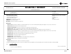
CE Series Power Amplifiers Crown International, Inc. DECLARATION of CONFORMITY TCF Technical Certificate No: C975CRI1.ABS Technical Construction File Route Issued By: Crown International, Inc. 1718 W. Mishawaka Road Elkhart, Indiana 46517 U.S.A.
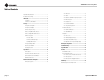
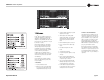
CE Series Power Amplifiers Table of Contents Important Safety Instructions ....................................................... 2 4.1.1 Bias Servo ..............................................................15 Declaration of Conformity ........................................................... 3 4.1.2 Fault .......................................................................15 1 Welcome .................................................... 5 4.1.3 Ultrasonic and Radio Frequency Protection ....
CE Series Power Amplifiers 1 Welcome • Versatile; handles a wide range of speaker impedances and outputs. Crown® CE Series amplifiers provide professional audio amplification for a wide range of applications, including digital cinema. The amplifiers are very affordable, and feature frontpanel controls for easy setup and use. They can be removed for security.
CE Series Power Amplifiers 2 Setup 2.1 Unpack Your Amplifier Please unpack and inspect your amplifier for any damage that may have occurred during transit. If damage is found, notify the transportation company immediately. Only you can initiate a claim for shipping damage. Crown will be happy to help as needed. Save the shipping carton as evidence of damage for the shipper’s inspection. We also recommend that you save all packing materials so you will have them if you ever need to transport the unit.
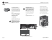
CE Series Power Amplifiers 2 Setup 2.4 Choose Input Wire and Connectors You have three choices of input connectors: 1/4-inch (6.35-mm) phone, 3-pin XLR, or barrier strip. You can also use either balanced or unbalanced wiring. Figure 2.3 shows balanced connector pin assignments for XLR and phone. Figure 2.4 shows unbalanced connector pin assignments for XLR and phone. Figure 2.5 shows barrier strip input wiring for a balanced signal.
CE Series Power Amplifiers 2 Setup 2.5 Choose Output Wire and Connectors Crown recommends using pre-built or professionally wired, high-quality, two- or four-conductor, heavy gauge speaker wires. They should be terminated with Neutrik Speakon NL4FC connectors (Figure 2.6) at one end and appropriate connectors to fit your speakers at the other end.
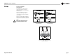
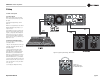
CE Series Power Amplifiers 2 Setup 2.6 Wire Your System 2.6.1 Stereo Mode Make sure the amplifier is turned off and the level controls are turned down before you wire the system. Typical input and output wiring is shown in Figure 2.9. INPUTS: Connect input wiring for each channel. OUTPUTS: Maintain proper polarity (+/–) on output connectors. Connect Channel-1 positive (+) speaker load to Channel-1 positive terminal of amp; repeat for negative (–). Repeat each channel wiring as for Channel 1.
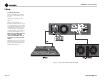
CE Series Power Amplifiers 2 Setup 2.6.3 Bridge-Mono Mode Make sure the amplifier is turned off and the level controls are turned down before you wire the system. Typical input and output wiring is shown in Figure 2.11. INPUTS: Connect input wiring to CH 1. OUTPUTS: Connect the speaker across the positive (+) output terminals. Do not use the negative (–) terminals when the amplifier is being operated in Bridge-Mono mode. Refer to Section 2.5 for output connector pin assignments.
CE Series Power Amplifiers 2 Setup 2.7 Input Sensitivity Switch A two-position Input Sensitivity switch is located on the back panel near the input connectors (Figure 2.12). Your amplifier is shipped from the factory with this switch set to the 1.4V position. At this setting, a 1.4V input signal will drive the amplifier to full power into an 8-ohm load when the level controls are turned to maximum.
CE Series Power Amplifiers 3 Operation 3.1 Precautions Your amplifier is protected from internal and external faults, but you should still take the following precautions for optimum performance and safety: 1. Before use, your amplifier first must be configured for proper operation, including input and output wiring hookup. Improper wiring can result in serious operating difficulties.
CE Series Power Amplifiers 3 Operation 3.2 Controls, Indicators and Connectors Figure 3.
CE Series Power Amplifiers 3 Operation 3.3 Front Panel Controls and Indicators Power Switch The power switch turns the amplifier on (“I”) or off (“O”). See Section 4.2.2 in this manual for more information on fault monitoring and suggestions for signalling device circuity. Note that dangerous voltages may still be present in the amplifier even when the power switch is in the off (“O”) position.
CE Series Power Amplifiers 4 Advanced Features and Options NOTE: For detailed information about these Crown amplifier features, please consult the Crown Amplifier Application Guide, available on the Crown website at www.crownaudio.com. 4.1 Protection Systems CE Series amplifiers are protected against shorted, open or mismatched loads; overloaded power supplies; excessive temperature; chain destruction phenomena; input overload damage; and high-frequency blowups.
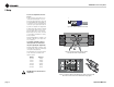
CE Series Power Amplifiers 4 Advanced Features and Options SST-SBSC (Summed Bass Stereo Crossover) Module See Figure 4.1. Features include: • Stereo biamp. • Ten user-specified crossover frequencies. • 12-, 18- and 24-dB/octave (Linkwitz-Riley) filters. • CD horn equalization. • Mono summing of sub-bass output for driving subs. SST-SBSC 4632T Like the SST-SBSC 3632T but for the JBL 4632T cinema speakers. SST-4622 See Figure 4.2.
CE Series Power Amplifiers 4 Advanced Features and Options 4.2.2 Fault Monitoring The Fault (RJ-11) jack, which looks like a telephone jack, is located on the back of your CE Series amplifier (Figure 4.3). It gives you an easy way to remotely monitor the amplifier’s fault status. To set up a circuit that will cause an LED to light whenever a fault status occurs, you can simply use the suggested circuit shown in Figure 4.4.
CE Series Power Amplifiers 4 Advanced Features and Options 4.3 Options 4.3.1 Accessories CE HANDLES Handles complement your amplifier’s appearance, aid in transportation, and facilitate rack mounting and removal. They are available from Crown’s Sales Department; just ask for “CE Handles.” CE-S1 Speakon to barrier output adapter. Compatible with CE versions CE 1000 and CE 2000 amplifiers (initial release). CE-S2 Speakon to 5-way binding post adapter.
CE Series Power Amplifiers 5 Principles of Operation For the sake of simplicity, only channel one of the amplifier is described. Signal is presented to the CE amplifier through one of three connectors when using the standard input module. Each channel is outfitted with a balanced XLR/phone jack and a barrier strip. These connectors are wired in parallel, which allows daisy chaining when needed.
CE Series Power Amplifiers 5 Principles of Operation + HI-VOLTAGE BOOTSTRAP TURN-ON DELAY TO CLIP INDICATOR CURRENT SOURCE COMPRESSOR CONTROL BIAS Figure 5.
CE Series Power Amplifiers 6 Troubleshooting CONDITION: Power indicator is off. POSSIBLE REASON CONDITION: Distorted sound. • The amplifier has lost AC power. POSSIBLE REASON: • The amplifier’s Power switch is off. • Load is wired incorrectly or Stereo/Mono mode switch is set incorrectly. Check both. • The amplifier’s power cord is not plugged in at either end. • • The amplifier’s circuit breaker has tripped.
CE Series Power Amplifiers 7 Specifications Minimum Guaranteed Power CE 1000 CE 2000 560 W 450 W 275 W 975 W 660 W 400 W 1,100 W 900 W 1,950 W 1,320 W CE 1000 CE 2000 ± 0.2 dB ± 0.2 dB 120 VAC, 60 Hz Units, Stereo mode, per channel, both channels driven 1 kHz with < 0.5% THD 2 ohms 4 ohms 8 ohms 120 VAC, 60 Hz Units, Bridge mono mode 1 kHz with 0.
CE Series Power Amplifiers 8 Service Crown amplifiers are quality units that rarely require servicing. Before returning your unit for servicing, please contact Crown Technical Support to verify the need for servicing. This unit has very sophisticated circuitry which should only be serviced by a fully trained technician. This is one reason why each unit bears the following label: CAUTION: To prevent electric shock, do not remove covers. No user serviceable parts inside.
CE Series Power Amplifiers 9 Warranty UNITED STATES & CANADA SUMMARY OF WARRANTY 3 AR YE Crown International, 1718 West Mishawaka Road, Elkhart, Indiana 46517-4095 U.S.A. warrants to you, the ORIGINAL PURCHASER and ANY SUBSEQUENT OWNER of each NEW Crown product, for a period of three (3) years from the date of purchase by the original purchaser (the “warranty period”) that the new Crown product is free of defects in materials and workmanship.
CE Series Power Amplifiers 9 Warranty 3 AR YE WORLDWIDE EXCEPT USA & CANADA SUMMARY OF WARRANTY Crown International, 1718 West Mishawaka Road, Elkhart, Indiana 46517-4095 U.S.A.
CE Series Power Amplifiers This page intentionally left blank.
CE Series Power Amplifiers Crown Factory Service Information Shipping Address: Crown Factory Service, 1718 W. Mishawaka Rd.