COM-TECH® Models: Com-Tech 210, 410, 810 & 1610 Some models may be exported under the name Amcron.® © 2001 by Crown Audio, Inc., P.O. Box 1000, Elkhart, IN 46515-1000 U.S.A. Telephone: 219-294-8000. Fax: 219-294-8329. Trademark Notice: Amcron®, BCA® and Crown ® are registered trademarks of Crown International, Inc. Other trademarks are the property of their respective owners.
Com-Tech Power Amplifiers This page intentionally left blank Page 2 Reference Manual
Com-Tech Power Amplifiers Important Safety Instructions 1) Read these instructions. 2) Keep these instructions. 3) Heed all warnings. 4) Follow all instructions. 5) Do not use this apparatus near water. 6) Clean only with a dry cloth. 7) Do not block any ventilation openings. Install in accordance with the manufacturer’s instructions. 8) Do not install near any heat sources such as radiators, heat registers, stoves, or other apparatus that produce heat.
3 YEAR THREE YEAR FULL WARRANTY 3 YEAR WORLDWIDE NORTH AMERICA SUMMARY OF WARRANTY The Crown Audio Division of Crown International, Inc., 1718 West Mishawaka Road, Elkhart, Indiana 46517-4095 U.S.A.
The information furnished in this manual does not include all of the details of design, production, or variations of the equipment. Nor does it cover every possible situation which may arise during installation, operation or maintenance. If your unit bears the name “Amcron,” please substitute it for the name “Crown” in this manual. If you need special assistance beyond the scope of this manual, please contact our Technical Support Group. Crown Technical Support Group Plant 2 SW, 1718 W. Mishawaka Rd.
Com-Tech Power Amplifiers CONTENTS 1 Welcome ............................................................................ 9 1.1 Unpacking ................................................................... 9 1.2 Features ....................................................................... 9 2 Facilities .......................................................................... 10 3 Installation ....................................................................... 12 3.1 Mounting ......................
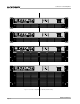
Com-Tech Power Amplifiers ILLUSTRATIONS 1.1 2.1 2.2 3.1 3.2 3.3 3.4 3.5 3.6 3.7 3.8 3.9 3.10 3.11 3.12 3.13 3.14 3.15 3.16 4.1 4.2 4.3 5.1 6.1 6.2 6.3 6.4 6.5 6.6 6.7 6.8 6.9 6.10 6.11 6.12 6.13 7.1 7.2 7.3 7.4 8.1 8.2 Reference Manual Com-Tech Amplifiers (120 VAC, 60 Hz Units) ............................. 8 Front Facilities ......................................................................... 10 Rear Facilities .........................................................................
Com-Tech Power Amplifiers Fig. 1.
Com-Tech Power Amplifiers 1 Welcome Congratulations on your purchase of a Com-Tech® commercial power amplifier. The Com-Tech series is a complete family of amplifiers with a wide range of power output capabilities. Com-Tech amplifiers can directly drive “constant voltage” lines, so you can avoid the expense, distortion and insertion loss associated with step-up transformers for distributed loudspeaker systems.
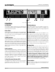
Com-Tech Power Amplifiers 2 Facilities Fig. 2.1 Front Facilities A. Filter Grille F. Enable Indicator A metal grille supports and protects the dust filter (B). To clean the dust filter, detach the grille by removing the screws that fasten it in place. This indicator lights when the amplifier has been enabled, or turned on, and AC power is available. The enable indicator will dim when the energy saving circuit is activated (see Section 4.2). B.
Com-Tech Power Amplifiers Fig. 2.2 Rear Facilities (Domestic Model Shown) J. Dual/Mono Switch For 8- and 4-ohm operation, remove the cover plate, if so equipped, then slide this switch to the center for Dual (two-channel) mode, to the left for Parallel-Mono mode or to the right for Bridge-Mono mode. WARNING: Do not change this switch unless the amplifier is turned off. Do NOT use the Bridge-Mono or Parallel-Mono modes unless both output mode switches (O) are set the same.
Com-Tech Power Amplifiers 3 Installation sions. This section covers basic Com-Tech installation procedures. All Com-Tech amplifiers are intended for rack mount installations using a commercial 19-inch (48.3-cm) EIA rack standard metal cabinet wired with a commercial grade electrical outlet box and receptacles. All Com-Tech Amplifiers utilize a convenient 3-foot long (0.9-m) power cord for such installations. Height A: 3.5 inches (8.9 cm) Models: Com-Tech 210 (All) Com-Tech 410 (North American) 3.
Com-Tech Power Amplifiers information in Section 7 to estimate the amplifier’s thermal dissipation for your application. In general, a North American Com-Tech 210 that dissipates more than 410 btu (110 kcal) per hour per unit will need additional cooling. If you are not sure, observe the ODEP indicators while the amplifier is operating under worst-case conditions. If the indicators dim, additional cooling is recommended. 17 in 43.2 cm IMPORTANT: Be sure the back of the amplifier is supported.
Com-Tech Power Amplifiers AIR FLOW BLOWER (OPTION 2) FRONT OF RACK DOOR EQUIPMENT RACK (SIDE VIEW) AIR FLOW BLOWER (OPTION 1) Fig. 3.3 Extra Cooling with a Rack-Mounted Blower because wire tends to cause less air restriction (perforated panels cause a minimum air restriction of 40%). A better choice for increasing the air flow behind a rack cabinet door is to use a “squirrel cage” blower.
Com-Tech Power Amplifiers remove the “Dual-Mono” mode switch cover and set the switch to the desired setting. Then replace the switch cover plate before restoring power. 8/4-ohm mode is commonly used to drive loudspeakers with impedances from 2 to 16 ohms. When using this output mode, appropriate load impedances will depend on the dual/mono mode that you select. The available dual/mono modes (Dual, Bridge-Mono and Parallel-Mono) will be described in sections that follow.
Com-Tech Power Amplifiers uted loudspeaker system, the constant voltage output varies with the output power rating of the amplifier. With 8/4-ohm output in Dual or Parallel-Mono mode, the Com-Tech 210 can drive a 25-volt line, the Com-Tech 410 can drive a 35-volt line, the Com-Tech 810 can drive a 50-volt line, and the Com-Tech 1610 can drive a 70volt line. Using Bridge-Mono mode, these voltage levels are doubled for a single channel.
Com-Tech Power Amplifiers WARNING: Both channels must be configured for the same output mode (8/4-ohm or 70-volt) before switching to Bridge-Mono mode. Channel 2 terminal. Do not connect the output grounds ( ). Also, the load must be balanced (neither side shorted to ground). Bridge-Mono wiring is very different from the other modes and requires special attention. First, turn the amplifier off. Then select Bridge-Mono mode by sliding the dual/mono switch to the BRIDGE MONO (right) position.
Com-Tech Power Amplifiers TURN OFF THE AMPLIFIER BEFORE CHANGING THE OUTPUT MODE SWITCHES. CHANNEL 1 8/4 OHM 70 VOLT 8/4 OHM 70 VOLT WARNING: BOTH CHANNELS MUST BE SET TO 70 VOLT MODE. CH1 CH2 NOT MIXER CH2 CH1 ES T S PR ADD A 14 GAUGE OR LARGER JUMPER BETWEEN THE CHANNEL 1 AND 2 POSITIVE (+) TERMINALS. BB REMOTE PUSH TO RESET RE E S + Programmable Input Processor (P.I.P.) 15 17 19 21 25 32 13 11 10 9 8 7 – + – 6 15 17 19 21 25 32 5 4 3 2 1 dB 0 13 .
Com-Tech Power Amplifiers CAUTION: When Parallel-Mono wiring is installed, do NOT operate in Dual or Bridge-Mono mode until the wiring is removed (especially the jumper wire). Failure to do so will result in high distortion and excessive heating. 3.3.2 Audio Input Connection The balanced inputs have a nominal impedance of 20 k ohms (10 k ohms unbalanced) and will accept the linelevel output of most devices.
Com-Tech Power Amplifiers 910 Ω dB + 0 A + .003 µf Balanced In –5 Balanced Out – –10 f 1µ .1 µf .05 µf .01 – 910 Ω µf –15 1.8 mH 1 Hz 10 Hz 100 Hz 1 kHz + 10 kHz Frequency B Fig. 3.10 Infrasonic Filter Capacitor Values Balanced In + .015 µf Balanced Out – – 1.8 mH Another problem to avoid is large levels of radio frequencies or RF in the input signal.
Com-Tech Power Amplifiers Use Good Connectors 1. To prevent possible short circuits, do not expose the loudspeaker cable connectors. 2. Do not use connectors that might accidentally tie two channels together when making or breaking connections (for example, a standard three-wire stereo phone plug). 3. Connectors that can be plugged into AC power receptacles should never be used. 4. Connectors with low current-carrying capacity should not be used. 5.
Com-Tech Power Amplifiers Consider the power handling capacity of your load before connecting it to the amplifier. Crown is not liable for damage incurred at any time due to overpowering. Fusing loudspeaker lines is highly recommended (see Section 3.3.5). Also, please pay close attention to Section 4.1, Precautions. .0002 .0004 RS SOURCE RESISTANCE (ohms) .0006 .001 You should always install loudspeaker cables of sufficient gauge (wire thickness) for the length used.
Com-Tech Power Amplifiers 7. If the size of the cable exceeds what you want to use, (1) find a way to use shorter cables, like using the IQ System, (2) settle for a lower damping factor, or (3) use more than one cable for each line. Options 1 and 2 will require the substitution of new values for cable length or damping factor in the nomograph. For option 3, estimate the effective wire gauge by subtracting 3 from the apparent wire gauge every time the number of conductors of equal gauge is doubled.
Com-Tech Power Amplifiers require a microphone and line level input for each channel. For more information on PIP modules, see Section 8. 1.0 1.2 1.4 1.6 20 2 3.4 AC Power Requirements 3000 15 2000 2.5 10 1500 8 3 1000 800 6 600 5 5 300 3 200 6 150 2 7 Example: Z = 8 ohms. Peak Power = 75 W 100 80 1.5 60 8 9 Answer: Fuse = 1.5 A 1 40 .8 10 30 .6 12 20 .5 15 14 .4 10 FUSE (amps) SPEAKER Z (ohms) 20 25 .2 SPEAKER RATING 16 .
Com-Tech Power Amplifiers 4 Operation 4.1 Precautions Com-Tech amplifiers are protected from internal and external faults, but you should still take the following precautions for optimum performance and safety: 1. Improper wiring for the Dual, Bridge-Mono and ParallelMono modes, as well as the 8/4-ohm and 70-volt output modes can result in serious operating difficulties. Refer Section 3.3.1 for details. 2.
Com-Tech Power Amplifiers Fig. 4.2 ODEP, IOC and Signal Presence Indicator States 4.3 Protection Systems Com-Tech amplifiers provide extensive protection and diagnostic capabilities. Protection systems include ODEP, “standby” and an AC circuit breaker. These features provide protection under any conditions. 4.3.1 ODEP Crown invented ODEP to solve two long-standing problems in amplifier design: to prevent amplifier shutdown during demanding operation, and to increase the efficiency of the output circuitry.
Com-Tech Power Amplifiers conditions, ODEP immediately limits the drive level until it falls within the SOA. Limiting is proportional and kept to an absolute minimum—only what is required to prevent output device damage. This level of protection enables Crown to increase output efficiency to never-before-achieved levels while greatly increasing amplifier reliability. The on-board intelligence is monitored in two ways.
Com-Tech Power Amplifiers Again, this should only be possible when operating outside rated conditions, as when the amplifier is used to drive a 1-ohm load, or when an input signal is clipped severely. SENSITIVITY SWITCH INSIDE ACCESS HOLE 0.77 V 4.4 Controls The Enable switch is located on the front panel so you can easily turn the amplifier on and off. If you ever need to make any wiring or installation changes, don’t forget to disconnect the power cord.
Com-Tech Power Amplifiers 4.5 Energy Saving Circuit Application The new CT-10 Series amplifiers incorporate a new feature to significantly decrease the use of energy when the amplifier is idle. The Energy Saving circuit allows the amplifier to cut back its energy consumption based on the signal level offered to the inputs. Over time, this circuitry provides the end user better value by saving on air conditioning requirements and utility expenses. This circuit is normally active at all times.
–Vcc LVA ONLY ONE CHANNEL SHOWN HS TEMP –Vcc B (ODEP) PNP LOW OUTPUT STAGE PNP HI OUTPUT STAGE D DISPLAY VARIABLE GAIN STAGE D E ERROR AMP ODEP TRANSLATOR A B C LVA BIAS CURRENT LIMIT (DISPLAY) NPN HI OUTPUT STAGE + C (ODEP) E (DISPLAY) OUTPUT NPN LOW OUTPUT STAGE A (ODEP) +Vcc P.I.P. BARRIER BLOCK +Vcc BALANCED Page 30 Fig. 5.
Com-Tech Power Amplifiers The protection mechanisms that affect the signal path are implemented to protect the amplifier under realworld conditions. These conditions are high instantaneous current, excessive temperature, and output device operation outside safe conditions. Two transistors act as a conventional current limiter, sensing current in the output stage. If current exceeds safe levels, the limiters remove the drive from the LVAs, limiting current in the output stage to a safe level.
Com-Tech Power Amplifiers 6 Specifications The following specifications apply to all models in Dual mode with 8-ohm loads and an input sensitivity of 26 dB unless otherwise specified. MAP at 1 kHz: This term refers to maximum average power in watts at 1 kHz with 0.1% THD. Full Bandwidth Power: This term refers to maximum average power in watts from 20 Hz to 20 kHz with 0.1% THD. 120 VAC, 60 Hz Units: These North American units have dedicated transformers for 120 VAC, 60 Hz power mains.
Com-Tech Power Amplifiers Indicators Protection Enable: This amber indicator shows the on/off status of the unit’s low-voltage power supply and the activation of the energy-saving mode. Com-Tech amplifiers are protected against shorted, open or mismatched loads; overloaded power supplies; excessive temperature, chain destruction phenomena, input overload damage and high-frequency blowups. They also protect loudspeakers from input/ output DC and turn-on/turn-off transients.
Com-Tech Power Amplifiers ments. Com-Tech 210 amplifiers are 3.5 inch (8.9 cm) high. North American models of Com-Tech 410 amplifiers are also 3.5 inch (8.9 cm) high. 50-Hz models of Com-Tech 410 amplifiers are 5.25 inch (13.3 cm) high. Com-Tech 810 amplifiers are 5.25 (13.3 cm) high. Com-Tech 1610 amplifiers are 7 inch (17.8 cm) high. (See Section 3.1 for more information). 100/120 VAC, 50/60 Hz Units: Com-Tech 210 : 31 pounds, 6 ounces (14.2 kg) net; 35 pounds, 8 ounces (16.1 kg) shipping weight.
Com-Tech Power Amplifiers Crown specifications are guaranteed for three years. In an effort to provide you with as much information as possible about the high power-producing capabilities of your amplifier, we have created the following power matrices. Minimum Guaranteed Power Specifications Crown’s minimum power specifications represent the absolute smallest amount of output power you can expect from your amplifier when it is driven to full output under the given conditions.
Com-Tech Power Amplifiers Dual 120 VAC, 60 Hz (both channels driven) Bridge-Mono (balanced output) Parallel-Mono 100/120 VAC, 50/60 Hz Dual (both channels driven) Bridge-Mono (balanced output) Parallel-Mono 220/240 VAC, 50/60 Hz Dual (both channels driven) Bridge-Mono (balanced output) Parallel-Mono Load in Ohms Dual/Mono Mode (Constant Voltage) AC Mains Com-Tech 410 – Minimum Guaranteed Power (Watts) Maximum Average FTC Continuous Average At 0.1% THD (See note 1) At 0.
Com-Tech Power Amplifiers Dual 120 VAC, 60 Hz (both channels driven) Bridge-Mono (balanced output) Parallel-Mono 100/120 VAC, 50/60 Hz Dual (both channels driven) Bridge-Mono (balanced output) Parallel-Mono 220/240 VAC, 50/60 Hz Dual (both channels driven) Bridge-Mono (balanced output) Parallel-Mono Load in Ohms Dual/Mono Mode (Constant Voltage) AC Mains Com-Tech 810 – Minimum Guaranteed Power (Watts) Maximum Average FTC Continuous Average At 0.1% THD (See note 1) At 0.
Com-Tech Power Amplifiers Load in Ohms Dual/Mono Mode Dual 120 VAC, 60 Hz (both channels driven) Bridge-Mono (balanced output) Parallel-Mono 100/120 VAC, 50/60 Hz Dual (both channels driven) Bridge-Mono (balanced output) Parallel-Mono 220/240 VAC, 50/60 Hz Dual (both channels driven) Bridge-Mono (balanced output) Parallel-Mono (Constant Voltage) AC Mains Com-Tech 1610 – Minimum Guaranteed Power (Watts) Maximum Average FTC Continuous Average At 0.1% THD (See note 1) At 0.
Com-Tech Power Amplifiers Maximum Power Specifications Crown’s maximum power specifications represent the largest amount of output power you can expect from your amplifier when it is driven to full output under the given conditions. These specifications can be used to prevent loudspeaker and hearing damage. The maximum power matrices include specifications for single cycle and 40-millisecond burst sine waves. Burst signals act like large transient peaks that are present in common source signals.
Com-Tech Power Amplifiers Dual 120 VAC, 60 Hz (both channels driven) Bridge-Mono (balanced output) Parallel-Mono 100/120 VAC, 50/60 Hz Dual (both channels driven) Bridge-Mono (balanced output) Parallel-Mono 220/240 VAC, 50/60 Hz Dual (both channels driven) Bridge-Mono (balanced output) Parallel-Mono Load in Ohms Dual/Mono Mode (Constant Voltage) AC Mains Com-Tech 410 – Maximum Power (Watts) Single Cycle Tone Burst 40 Millisecond Tone Burst At less than 0.05% THD (See note 1) At 0.
Com-Tech Power Amplifiers Dual 120 VAC, 60 Hz (both channels driven) Bridge-Mono (balanced output) Parallel-Mono 100/120 VAC, 50/60 Hz Dual (both channels driven) Bridge-Mono (balanced output) Parallel-Mono 220/240 VAC, 50/60 Hz Dual (both channels driven) Bridge-Mono (balanced output) Parallel-Mono Load in Ohms Dual/Mono Mode (Constant Voltage) AC Mains Com-Tech 810 – Maximum Power (Watts) Single Cycle Tone Burst 40 Millisecond Tone Burst At less than 0.05% THD (See note 1) At 0.
Com-Tech Power Amplifiers Dual 120 VAC, 60 Hz (both channels driven) Bridge-Mono (balanced output) Parallel-Mono 100/120 VAC, 50/60 Hz Dual (both channels driven) Bridge-Mono (balanced output) Parallel-Mono 220/240 VAC, 50/60 Hz Dual (both channels driven) Bridge-Mono (balanced output) Parallel-Mono Load in Ohms Dual/Mono Mode (Constant Voltage) AC Mains Com-Tech 1610 – Maximum Power (Watts) Single Cycle Tone Burst 40 Millisecond Tone Burst At less than 0.05% THD (See note 1) At 0.
Com-Tech Power Amplifiers +2 +1 0 –1 1 watt –2 8 ohm 4 ohm dB –3 –4 –5 –6 –7 10 100 1K 10 K 100 K FREQUENCY (Hz) Fig. 6.9 Typical Frequency Response 1400 1200 1000 800 600 400 8 ohm 200 100 0 100 20 1K 10 K 20 K FREQUENCY (Hz) Fig. 6.10 Typical Damping Factor 504.0 126.8 6 dB MILLIOHMS 31.8 8.0 2.0 10 100 1K 10 K 100 K FREQUENCY (Hz) Fig. 6.
Com-Tech Power Amplifiers TEF ® Measurement +45˚ 0˚ –45˚ 100 TECHRON TEF ® 1K 10 K 20 K FREQUENCY (Hz) Fig. 6.12 Typical Phase Response TEF ® Measurement –66 –72 –78 –84 dB –90 –96 –102 100 TECHRON TEF ® 1K 10 K 20 K FREQUENCY (Hz) Fig. 6.
Com-Tech Power Amplifiers 7 AC Power Draw and Thermal Dissipation “Soft-Start” inrush current limiting, protects the house circuit breaker when several amps are turned on simultaneously. • Duty cycle of rock ‘n’ roll is 30%. This section provides detailed information about the amount of power and current drawn from the AC mains by Com-Tech amplifiers and the amount of heat produced under various conditions.
Com-Tech Power Amplifiers Com-Tech 410 L O A D 8 Ohm Dual / 16 Ohm Bridge-Mono / 4 Ohm Parallel-Mono 4 Ohm Dual / 8 Ohm Bridge-Mono / 2 Ohm Parallel-Mono Duty Cycle AC Mains Power Draw (Watts) 50% 390 4.7 40% 320 3.8 30% 250 20% 10% Current Draw (Amps) Thermal Dissipation 100-120 V 220-240 V btu/hr kcal/hr AC Mains Power Draw (Watts) 2.1 550 140 410 4.9 1.7 470 120 335 4.0 3.0 1.4 385 100 265 180 2.2 1.0 305 80 110 1.3 0.
Com-Tech Power Amplifiers 8 Accessories 8.1 PIP and PIP2 Modules For more information on these or other PIPs under development, contact your local dealer or Crown’s Technical Support Group. One advantage of Crown PIP2 compatible amplifiers is the ability to customize them using PIP (Programmable Input Processor) and PIP2 modules. The PIPs shown here may be used in any Crown PIP2-compatible amplifier. PIPs carrying the PIP2 logo have been configured with an extended, PIP2-enhanced feature set.
Com-Tech Power Amplifiers removable barrier block connectors for quick, solderless connections. P.I.P.-BEQX Same as P.I.P.-BEQC but with XLR connectors. IQ-PIP-USP2 is an IQ2-series component. This means it supports Crown’s UCODE protocol and requires an IQ System with an IQ2-compatible IQ interface. UCODE (universal code) enables users and third parties to develop custom software objects to control and monitor IQ2-compatible components like the IQ-PIP-USP2. P.I.P.
Com-Tech Power Amplifiers 8.2 R.S.V.P. Module P.I.P.-PA permits the unique capability of adding one mic/ line input directly to each channel of an amplifier. With phantom power for microphones, this mic/line input may be remotely switched from mic to line priorities. R.S.V.P. The R.S.V.P. (Remote Switching Voltage Provider) can be used in applications requiring remote power turn on/ off of banks of amplifiers. Each R.S.V.P. can control up to 20 CT-10 Series amplifiers and/or daisy chain to other R.S.V.P.
Com-Tech Power Amplifiers 9 Service This unit has very sophisticated circuitry which should only be serviced by a fully trained technician. This is one reason why each unit bears the following label: Your repaired unit will be returned via UPS ground. Please contact us if other arrangements are required. CAUTION: To prevent electric shock, do not remove covers. No user serviceable parts inside. Refer servicing to a qualified technician. 9.
Crown Factory Service Information Shipping Address: Crown Audio, Inc., Factory Service, Plant 2 SW, 1718 W. Mishawaka Rd.