I-Tech Series I-T4000 Operation Manual I-T6000 I-T8000 Obtaining Other Language Versions: To obtain information in another language about the use of this product, please contact your local Crown Distributor. If you need assistance locating your local distributor, please contact Crown at 574-294-8000. This manual does not include all of the details of design, production, or variations of the equipment.
I-Tech Series Power Amplifiers Important Safety Instructions Wichtige Sicherheitsinstruktionen Importantes Instructions de Sécurité Instrucciones de Seguridad Importantes 1) 2) 3) 4) 5) 6) 7) 8) 9) 10) 11) 12) 13) 14) 15) 16) 17) 18) page 2 Read these instructions. Keep these instructions. Heed all warnings. Follow all instructions. Do not use this apparatus near water. Clean only with a dry cloth. Do not block any ventilation openings.
I-Tech Series Power Amplifiers DECLARATION of CONFORMITY Crown International, Inc. ISSUED BY: Crown International, Inc. 1718 W. Mishawaka Road Elkhart, Indiana 46517 U.S.A. FOR COMPLIANCE QUESTIONS ONLY: Sue Whitfield 574-294-8289 swhitfield@crownintl.
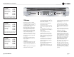
I-Tech Series Power Amplifiers Getting Started With I-Tech Welcome! Operating your I-Tech amplifier can be as simple or advanced as you wish. Right out of the box, it works like any other amplifier with stereo loudspeaker loads. • For bridge-mono operation, see page 5. • If you want to control and monitor the amplifier with Crown’s IQ System® software, see Section 4.5.4. If you are going to use SystemArchitect, please follow the information included with System Architect.
I-Tech Series Power Amplifiers Quick-Start Guide: Bridge-Mono Wiring Let’s assume that you unpacked and installed your amplifier with the proper cooling. If not, see Section 2 in this manual. We’ll also assume that you will operate the amplifier in BridgeMono. Basically you will turn on the amp, enable Bridge-Mono mode with the LCD Control Screen, turn off the amp, wire it, and turn it back on. 1. Be sure that no cables are connected to the amplifier.
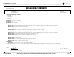
I-Tech Series Power Amplifiers Table of Contents Important Safety Instructions ............................................................2 4.3 Presets ..................................................................................22 Declaration of Conformity..................................................................3 4.4 Digital-Audio Options (AES/EBU)..........................................22 Getting Started with I-Tech ................................................................
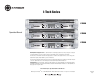
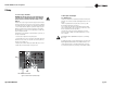
I-Tech Series Power Amplifiers I-T4000 20 Hz - 20 kHz Power 2-ohm Dual (per ch.) 4-ohm Dual (per ch.) 8-ohm Dual (per ch.) 1,800W 2,000W 1,250W 3,600W 4,000W 4-ohm Bridge 8-ohm Bridge Menu/Exit Prev Next 1 2 20 Hz - 20 kHz Power refers to guaranteed minimum power in watts with 0.35% THD. 1 Welcome I-T6000 20 Hz - 20 kHz Power 2-ohm Dual (per ch.) 4-ohm Dual (per ch.) 8-ohm Dual (per ch.
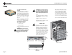
I-Tech Series Power Amplifiers 2 Setup 2.1 Unpack and Install Your Amplifier Please unpack and inspect your amplifier for any damage that may have occurred during transit. If damage is found, notify the transportation company immediately. Only you can initiate a claim for shipping damage. Crown will be happy to help as needed. Save the shipping carton as evidence of damage for the shipper’s inspection.
I-Tech Series Power Amplifiers 2 Setup 2.2 Connecting to AC Mains WARNING: The third (ground) prong of the supplied AC power cord connector is a required safety feature. Do not attempt to disable this ground connection by using an adapter or other methods. Amplifiers don’t create energy. The AC mains voltage and current must be sufficient to deliver the power you expect.
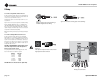
I-Tech Series Power Amplifiers 2 Setup 2.3.2 Choose Input Wire and Connectors Crown recommends using pre-built or professionally wired, balanced line (two-conductor plus shield), 22-24 gauge cables and connectors. Use 3-pin male XLR connectors. Unbalanced line may also be used but may result in noise over long cable runs. Figure 2.4 shows connector pin assignments for balanced analog wiring or AES/EBU digital wiring. The use of standard analog cable with AES/EBU will result in diminished performance.
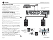
I-Tech Series Power Amplifiers 2 Setup 2.3.4 Stereo Mode Wiring Typical input and output wiring is shown in Figure 2.8. IMPORTANT: Turn off the amplifier and unplug its power cord. INPUTS: Choose one of these options: • Connect analog input wiring for both channels. • Connect an AES/EBU digital signal to the AES/EBU connector. OUTPUTS: Maintain proper polarity (+/–) on output connectors. Use Class 2 output wiring. Figure 2.8 shows how to wire stereo speakers to the binding posts.
I-Tech Series Power Amplifiers 2 Setup 2.3.5 Bridge-Mono Mode Overview: Turn on the amp, enable Bridge-Mono mode using the LCD Control Screen, turn off the amp, wire it, and turn it back on. 1. Be sure that no cables are connected to the amplifier. Turn on the front-panel power switch. The LCD Control Screen will light up (Figure 2.11). 2. Under the LCD Control Screen, press the Menu/Exit button. Press the Next button until you see OUTPUT MODE on the screen. 3. Press an Encoder knob to select BRIDGE MONO.
I-Tech Series Power Amplifiers 3 Operation 3.1 Protecting Your Speakers It's wise to avoid clipping the amplifier signal. Not only does clipping sound bad, it can damage high-frequency drivers. To prevent clipping, use IQwic™ or System Architect software to enable or display the peak voltage limiter and average power limiter in your amplifier’s built-in DSP. That way, no matter how strong a signal your mixer produces, the amplifier output will not clip.
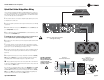
I-Tech Series Power Amplifiers 3 Operation 3.4 Front Panel Controls and Indicators A. Cooling Vents Front-to-rear forced airflow through foam dust filter. LCD Control Screen and Controls B. LCD Control Screen Integrated LCD with white backlight, controls amplifier setup and operation. The LCD Control Screen and its controls let the user adjust the amplifier's attenuation and muting, configure the amp, set up and view error monitoring (such as temperature and load supervision), and recall DSP presets.
I-Tech Series Power Amplifiers 3 Operation G. Reset Switch/Circuit Breaker If the current draw of the amplifier exceeds safe limits, this breaker automatically disconnects the power supply from the AC mains. The switch resets the circuit breaker. OUTPUTS SECTION 3.5 Back Panel Controls, Indicators and Connectors D. 4-Pole Speakon Output Connectors Two high-current, 50A Neutrik® Speakon NL4MLP (mates with NL4FC and NL4), one per channel. Class 2 output wiring required. A.
I-Tech Series Power Amplifiers 4 Advanced Operation 4.1 Advanced Operation Table of Contents............16 4.2 Navigating the LCD Control Screen ...................... 17 4.2.1 Introduction........................................................................ 17 4.2.2 Basic Menu........................................................................ 17 4.2.3 Advanced Menu................................................................. 18 4.2.4 Monitor Menu ..............................................
I-Tech Series Power Amplifiers 4 Advanced Operation 4.2 Navigating the LCD Control Screen 4.2.1 Introduction The LCD Control Screen and its controls let you configure the amplifier and access many features that before were available only through a remote computer. Also, you can recall DSP presets for certain loudspeaker models. (Some DSP parameters cannot be adjusted with the LCD Control Screen. That is done in System Architect or IQwic.) Figure 4.1 shows the parts of the LCD Control Screen.
I-Tech Series Power Amplifiers 4 Advanced Operation Presets: A preset is a group of DSP and amplifier settings for a particular speaker. Turn an Encoder to view Presets 1 through 20. To recall a preset, press the Encoder, then press and hold the Encoder to confirm. For more information on presets, see Section 4.3. The preset currently in use is displayed in the upper right corner. (A) Active means that the amplifier is operating exactly according to that preset.
I-Tech Series Power Amplifiers 4 Advanced Operation Peak Voltage Limiter: Limits the peak output voltage to a level that you set, either OFF or 0 to 255 volts. Press the Encoder to turn on the Limiter. Once it’s on, turn the Encoder to set the voltage. Additional controls, such as attack and release, are available through IQwic or System Architect. AES/EBU Input Trim: Sets the gain of the AES/EBU digital input signal. Turn an Encoder to change the gain. AES/EBU Input Trim 12.0 dB 13.
I-Tech Series Power Amplifiers Bandpass Gain: In each channel of the I-Tech’s DSP, just before the output limiter and after the preceding filter, is a gain block (not shown on the Signal Path block diagram). Bandpass Gain adjusts the gain of this block. 4.2.4 MONITOR MENU This menu lets you monitor the status of the amplifier. Starting from the Attenuation Screen, press Menu, then press Prev. Or, starting from the Advanced Menu screen, press Next to go to the Monitor Menu screen.
I-Tech Series Power Amplifiers 4 Advanced Operation Clip Errors: This screen lets you view clip errors without using IQwic or System Architect. A clip error occurs if the number of clip events exceeds the value set with the Count slider (within the time set by the Time slider) on the Error Reporting Page of the IQwic Control Panel or Amplifier Settings in System Architect. High Limit Load Errors: This screen lets you view high limit load errors without using the control software.
I-Tech Series Power Amplifiers 4 Advanced Operation MENU TREE Attenuation - Mute - Lockout 4.2.5 Operation Examples Menu button Operation Example 1 How to set the CH1 input sensitivity using the LCD Control Screen: 1. After power-up, press Menu/Exit. The first menu item appears: the Contrast screen. 2. Press Next until you see “CH1 Sensitivity.” 3. Turn an Encoder to set the sensitivity. NOTE: If you do not see the sensitivity you want, try changing the Maximum Analog Input level (see below). 4.
I-Tech Series Power Amplifiers 4 Advanced Operation 4.3 Presets We will describe each type of preset in detail. 4.3.1 Introduction Your I-Tech amplifier has a wide variety of onboard Digital Signal Processing (DSP). Some applications for this DSP are speaker configuration (setting the drive levels, frequency bands, delays and limiting for your particular speakers), EQ, filtering, compression, and much more. Those functions are described in Section 4.6.
I-Tech Series Power Amplifiers 4.5 Network Setup Wizard The network setup wizard can assist you in setting up your TCP/IQ network for the first time. Using the wizard, you can address your components and be informed of addressing and other errors in the system. Please note that this wizard is designed to work with devices that are on the same physical network segment as the computer it is running on. It will not work through a router.
I-Tech Series Power Amplifiers 4 Advanced Operation 4.6 Software-Controllable Onboard DSP Crown’s latest-generation Digital Signal Processing is built into the I-Tech amplifier. Its 24-bit/96kHz converters offer extremely low noise and extended dynamic range. When you use an I-Tech amp, the loudspeaker processors, crossovers, limiters and delays are in the onboard DSP – so you don’t need those rack-mounted devices. This drastically cuts setup time, commissioning, rack space and costs.
I-Tech Series Power Amplifiers 4 Advanced Operation 4.6.14 Input Signal Compressor/Limiter An input signal compressor/limiter is available for each channel. Five parameters control this feature: Threshold: Sets the level, in absolute voltage, which the limiter will allow from the amplifier. The range is from 12 Vpk to 255 Vpk. Enable: Enables or disables this function. Attack Time: Sets the attack time of the limiter.
I-Tech Series Power Amplifiers 4 Advanced Operation control. When the memory backup is disabled, the amplifier stops storing changes made to its settings. When the next power-up occurs the amplifier uses the settings that were active when the backup feature was disabled. 4.6.24 Noise Generator CAUTION: Care should be taken to backup “safe” levels for the input attenuator controls. It is possible for the memory backup feature to be disabled with “unsafe” levels stored.
I-Tech Series Power Amplifiers 5 Troubleshooting CONDITION: Power indicator is off and power switch is not illuminated. POSSIBLE REASON • The amplifier has lost AC power. • The amplifier is not plugged into the power receptacle. • Rear-panel breaker is off. • The amplifier is becoming too hot for safe operation. Allow amplifier to cool. Check for loads less than 2 ohms, and for excessive input levels. Check for proper ventilation. CONDITION: Fault indicator is flashing.
I-Tech Series Power Amplifiers 5 Troubleshooting CONDITION: Data indicator not flashing, even though host computer IQ software is active. CONDITION: No sound, even though the amp has power. Power LED is on without flashing and the amp is receiving an input signal. Signal indicator is on or flashing. POSSIBLE REASON: • POSSIBLE REASON: • Speakers not connected. • Open circuit due to speaker failure. • There is a short on the amplifier output.
I-Tech Series Power Amplifiers 6 Specifications 6.1 Performance Minimum Guaranteed Power 20 Hz - 20 kHz with 0.35% THD Stereo, 2 ohms (per ch.) Stereo, 4 ohms (per ch.) Stereo, 8 ohms (per ch.) Bridge mono, 4 ohms Bridge mono, 8 ohms Performance Input Sensitivity (volts RMS) for rated output Voltage Gain for full rated power at 8 ohms I-T4000 I-T6000 I-T8000 1800W 2000W 1250W 3600W 4000W 2500W 3000W 1500W 5000W 6000W 3500W 4000W 2100W 7000W 8000W I-T4000 I-T6000 I-T8000 Adjustable in 0.
I-Tech Series Power Amplifiers 6 Specifications Performance I-T4000 I-T6000 I-T8000 Damping Factor (8 ohms): 20 Hz to 100 Hz > 5000 > 5000 > 5000 Crosstalk (below rated power, 20 Hz to 1 kHz) > 80 dB > 80 dB > 80 dB Common Mode Rejection (CMR) (20 Hz to 1 kHz) > 50 dB > 50 dB > 50 dB DC Output Offset (Shorted input) < ± 3 mV < ± 3 mV < ± 3 mV 20 kilohms balanced, 10 kilohms unbalanced 20 kilohms balanced, 10 kilohms unbalanced 20 kilohms balanced, 10 kilohms unbalanced 1-2-4-8-16 oh
I-Tech Series Power Amplifiers 6 Specifications 6.2 Charts Figure 6.1 Typical Frequency Response (1W) Figure 6.2 Typical Crosstalk vs. Frequency Figure 6.3 Typical Damping Factor vs.
I-Tech Series Power Amplifiers 7 AC Power Draw and Thermal Dissipation I-Tech 4000 AC Current Draw and Thermal Dissipation: Pink noise 12dB crest factor, bandwidth limited 22Hz to 22kHz. Typical line impedance used. Data based on both channels driven. I-T4000 120VAC Load Idle (sleep mode) Idle (awake) 1/8th Power Pink Noise Typical of program material just at clip. 1/3rd Power Pink Noise Typical of program material with severe clipping.
I-Tech Series Power Amplifiers 7 AC Power Draw and Thermal Dissipation I-Tech 6000 AC Current Draw and Thermal Dissipation: Pink noise 12dB crest factor, bandwidth limited 22Hz to 22kHz. Typical line impedance used. Data based on both channels driven. I-T6000 120VAC Load Idle (sleep mode) Idle (awake) 1/8th Power Pink Noise Typical of program material just at clip. 1/3rd Power Pink Noise Typical of program material with severe clipping.
I-Tech Series Power Amplifiers 7 AC Power Draw and Thermal Dissipation I-Tech 8000 AC Current Draw and Thermal Dissipation: Pink noise 12dB crest factor, bandwidth limited 22Hz to 22kHz. Typical line impedance used. Data based on both channels driven. I-T8000 120VAC Load Idle (sleep mode) Idle (awake) 1/8th Power Pink Noise Typical of program material just at clip. 1/3rd Power Pink Noise Typical of program material with severe clipping.
I-Tech Series Power Amplifiers 8 Advanced Features 8.1 Protection Systems Your Crown amplifier provides extensive protection and diagnostic capabilities, including thermal level control, fault indicators, highpass filtering, DC protect, AC under/over voltage protection, inrush limiting, and variablespeed fans. 8.1.1 Thermal Level Control (TLC) If the amplifier becomes too hot for safe operation, the TLC will engage the input compressor and the clip LED will illuminate.
I-Tech Series Power Amplifiers 9 Appendix A: Network Basics 9.1 TCP/IQ and HiQnet Networks Background: A Local Area Network (LAN) is a group of computers in a venue that share data, either through cables or via wireless transmission. Ethernet is a popular LAN communication protocol for PCs. An audio network is a Local Area Network made of audio devices and one or more computers. A subnet is a small network within a larger network.
I-Tech Series Power Amplifiers Network Addresses Each component in a TCP/IQ or HiQnet network has three addresses to identify it: • Media Access Control (MAC) Address • Internet Protocol (IP) Address • IQ or HiQnet Address AUDIO NETWORK VENUE NETWORK Let’s explain each identifier. MAC address: Short for Media Access Control, MAC is an address for an audio component that is burned into firmware in the component by its manufacturer, and cannot be changed.
I-Tech Series Power Amplifiers 9 Appendix B: Setting Sensitivity for Best Gain Staging Optimized system gain structure maximizes signal to noise within the system. Adjusting your amplifier to fit within an optimized system gain structure is accomplished by properly setting both the sensitivity and attenuation controls within the amplifier. I-Tech amplifiers offer 149 sensitivity and gain settings allowing very fine adjustment of the amplifier’s gain and voltage sensitivity.
I-Tech Series Power Amplifiers 10 Service Crown amplifiers are quality units that rarely require servicing. Before returning your unit for service, please contact Crown Technical Support to verify the need for servicing. ber to transport the unit in the original factory pack. A list of authorized service centers in your area can be obtained from Crown Factory Service, or online from http://www.crownaudio.com/support/servcent.htm.
I-Tech Series Power Amplifiers 11 Warranty UNITED STATES & CANADA SUMMARY OF WARRANTY Crown International, 1718 West Mishawaka Road, Elkhart, Indiana 46517-4095 U.S.A. warrants to you, the ORIGINAL PURCHASER and ANY SUBSEQUENT OWNER of each NEW Crown product, for a period of three (3) years from the date of purchase by the original purchaser (the “warranty period”) that the new Crown product is free of defects in materials and workmanship.
I-Tech Series Power Amplifiers 11 Warranty WORLDWIDE EXCEPT USA & CANADA SUMMARY OF WARRANTY WHAT THE WARRANTOR WILL DO Crown International, 1718 West Mishawaka Road, Elkhart, Indiana 46517-4095 U.S.A.
I-Tech Series Power Amplifiers PRODUCT REGISTRATION Crown Audio, Inc. 1718 W. Mishawaka Rd. Elkhart, IN 46517-9439 Phone: 574-294-8000 Fax: 574-294-8329 www.crownaudio.com Online registration is also available at http://crownweb.crownintl.com/webregistration. Warranty is only valid within the country in which the product is purchased. When this form is used to register your product, it may be mailed or faxed. Crown Audio, Inc.
I-Tech Series Power Amplifiers THIS PAGE INTENTIONALLY LEFT BLANK page 44 Operation Manual
I-Tech Series Power Amplifiers Crown Audio Factory Service Information Shipping Address: Crown Audio Factory Service, 1718 W. Mishawaka Rd., Elkhart, IN 46517 PLEASE PRINT CLEARLY SRA #: __________________(If sending product to Crown factory service.
THIS PAGE INTENTIONALLY LEFT BLANK
THIS PAGE INTENTIONALLY LEFT BLANK