- MC Modules IQ-MC8 & IQ-MC4A © 2006 by Crown Audio ®, Inc., 1718 W. Mishawaka Rd., Elkhart, IN 46517-9439 U.S.A. Telephone: 574-294-8000. Fax: 574-294-8329. Trademark Notice: IQ2 , SmartAmp and PIP are trademarks. Crown, Crown Audio and IQ System are registered trademarks of Crown International. Other trademarks are the property of their respective owners.
IQ-MC Modules The infor mation furnished in this manual does not include all of the details of design, production, or var iations of the equipment. Nor does it cover every possib le situation which may arise during installation, operation or maintenance. If you need special assistance beyond the scope of this manual, please contact Crown Technical Support. Crown Technical Support 1718 W. Mishawaka Rd., Elkhart, Indiana 46517 U.S.A.
IQ-MC Modules DECLARATION OF CONFORMITY Crown Audio, Inc. 1718 W. Mishawaka Rd. Elkhart, IN 46517 U.S.A. Susan Whitfield 574-294-8289 swhitfield@crownintl.
IQ-MC Modules Content 1 Welcome .............................. 5 2 Controls, Connectors & Indicators 6 3 Installation ........................... 7 3.1 Prepare the MC-IQ Module ................... 7 3.2 Install the Wiring ................................... 8 3.3 Adjust System Levels .......................... 10 4 Operation ............................. 11 4.1 Hardware ............................................. 11 4.1.1 Data Signal Presence Indicator .... 11 4.1.2 Preset Indicator ....................
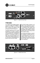
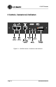
IQ-MC Modules Figure 1.1 IQ-MC4A Front Panel 1 Welcome The IQ-MC4A and IQ-MC8 modules connect CTs 4200 and CTs 8200 amplifiers to the IQ Bus of an IQ System ®, allowing the amplifier to be controlled and monitored via IQ. The IQ-MC module is an IQ2 ™ series component. This means it supports Crown’s IQ2 protocol and requires an IQ System with an IQ2 -compatible IQ interface.
IQ-MC Modules 2 Controls, Connectors & Indicators Figure 2.
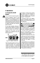
IQ-MC Modules 3 Installation 3.1 Prepare the IQ-MC Module First, turn off and unplug the amplifier. Set the IQ address switch S1. By giving each IQ component a unique address, it can be individually controlled and monitored. Whenever the IQ System wants to send a command to just one IQ component, it first sends its address and then the command down the IQ Bus. 1 2 4 8 16 32 64 128 VALUE S1 has eight segments because it actually contains eight tiny switches inside.
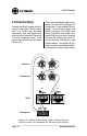
IQ-MC Modules 3.2 Install the Wiring Connect the IQ-MC module to the IQ system via the IQ Bus. The IQ components in a IQ Bus loop are wired sequentially. The loop begins and ends with the IQ interface. The output of one IQ component “loops” to the input of the next and so on as shown in Figure 3.2. There are three different types of connectors used for IQ Bus wiring on IQ components. These include DIN connectors, screw terminal plugs, and RJ-45 connectors.
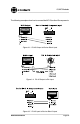
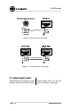
IQ-MC Modules The following examples show how to connect the MC-IQ to other IQ components: Figure 3.3 RJ-45 Output to Barrier Block Input Figure 3.4 RJ-45 Output to Din Input Figure 3.
IQ-MC Modules Figure 3.6 RJ-45 Input to Din Output Figure 3.7 RJ-45 Output to RJ-45 Intput 3.3 Adjust System Levels Adjust attenuator levels both on the amplifier and on the IQ-MC module Page 10 control panels within your IQ software for optimum system gain.
IQ-MC Modules 4 Operation With the IQ-MC option, your CTs 4200 and CTs 8200 amplifiers can be monitored and controlled from a remote location through the use of an IQ System. This module features SmartAmp ™ capabilities which will enable the amplifier to function automatically. For example, the IQ-MC module can automatically limit the audio signal, also detect and report various problems. In addition, the IQ-MC Load Supervision feature has the ability to verify the status of the loads in real time.
IQ-MC Modules trolled via software or may be programmed to switch when a fail condition is present on any channel.* The high-impedance (10 K ohm) AUX input can sense logic signals and can be programmed to activate system mute or report fault conditions when a logic high is present. (See Section 5.2.2 for more information.) All amplifier channel’s output can be monitored as a balanced line level signal which is sent to pins 1 and 6 of the RJ-11 connector (software selectable). 4.1.
IQ-MC Modules -To clear all memory and set to factory default presets: ture has a range from +20 dBu to –40 dBu in ½-dB steps. Remove all input signals. Press in and hold the switch while applying power to the unit. The settings will be reset to factory default, with the firmware rewriting to EEPROM memory. Important: This action will re-write the memory and erase stored presets. With the button held in and power applied, the DATA and PRESET indicators will both be lit.
IQ-MC Modules 4.3.6 Ready/Standby Control Each channel’s output relay can be independently turned on and off. However, the Dual/Bridge mode of the amplifier cannot be controlled via software. 4.3.7 Signal Mute 4.3.13 Error Reporting The output signal of each channel can be independently muted. This function typically provides 80 dB or more of attenuation.
IQ-MC Modules Thermal: You can choose to be warned if the thermal level rises above a predetermined level. The Threshold control lets you set the thermal level above which an error message will be reported. The range is from 1 to 100%. point is located before the gain control stage. The range is from +16 dBu to –40 dBu. Fault: You can choose to be warned when an amplifier “fault” condition occurs when a channel fails. Attack Time: Sets the attack time of the compressor.
IQ-MC Modules On/Off: Turns the limiter on or off. Average Power Threshold: The threshold is adjustable from 10 to 1000 watts.** Nominal Load Impedance: The nominal load impedance is settable from 1 to 1000 ohms, and should be set to correspond to the nominal impedance rating of the load connected to the respective channel. Attack Time: Adjustable from 1 second to 30 seconds in 1 second increments. Release Time: Adjustable from 1 second to 30 seconds in 1 second increments. 4.
IQ-MC Modules CH 8 Figure 4.1 MC-IQ Signal Flow Block Diagram 5 IQ Audio In Depth This section provides additional information about Crown’s IQ System with special guides to aid in the installation and use of the IQ-MC module. For more information about any of these topics, contact Crown Technical Support. IQ Bus loops or zones. Dividing the sound system into different zones, each with its own IQ Bus loop, can have several advantages.
IQ-MC Modules The IQ-MC module can be connected to the IQ Bus with inexpensive twisted-pair wiring (shielded or unshielded). If fiber optic wiring is required contact Crown Technical Support (see page 28). Here are some guidelines for twistedpair wiring: • Use shielded twisted-pair wire at least 26 AWG in size when interference is a problem. The wire should be of good quality and should have low capacitance—30 picofarads/foot or less is good.
IQ-MC Modules 5.2.1 AUX Output When the auxiliary feature is turned on by the IQ for Windows software +15 VDC is supplied across pins 3 (ground) and 4 (+). A total of 70 milliamps of current is available. The smart switch mosfet protects against shorts (see Figure 5.1). There are many possible uses for the AUX output. For example, it can be used to turn on auxiliary cooling fans. To do this the AUX connector might be used to close a relay. The relay would then turn the fans on or off.
IQ-MC Modules By monitoring the operating condition of amplifiers with the IQ System software, the need for additional cooling would be apparent. The same software could then be used to turn on the appropriate AUX connector. (For more information about turning the auxiliary feature on/off, consult the IQ for Windows software documentation.) Figure 5.4 demonstrates how multiple amplifiers can be monitored using the Listen Bus.
IQ-MC Modules When wiring RJ-11 connectors, it is good practice to follow the USOC protocol for RJ-11 connector cable. This protocol assigns wire colors as follows: 1 white-green 4 white-blue 2 white-orange 5 orange-white 3 blue-white 6 green-white When wiring RJ-45 connectors, it is good practice to follow the EIA/TIA 568B protocol for RJ-45 connector cable.
IQ-MC Modules This procedure should work well for most applications. However, some applications can be a little more difficult. Some very low-level and/or low duty-cycle signals may not adequately “test” the load. Lab and situation testing have shown output levels as small 40 dB below rated amplifier output to be enough for most low-impedance loads. Higher impedance loads such as those used in “lightly-loaded” 70V distribution lines may require signal level near 20 dB below rated output.
IQ-MC Modules 6 Specifications General IQ Bus Data Communication Internal Controls: An 8-segment DIP switch sets the IQ address (decimal range: 1–250)*.
IQ-MC Modules 7 IQ Address Tables The following pages in this section contain lookup tables for every valid IQ address. The valid addresses are 1 to 250. Remember that address “0” (zero) will put the IQ-MC into a standalone mode where it is invisible to the IQ System and acts like a “dumb” balanced audio input. Do not use an address number higher than 250! Addresses above 250 are reserved for special system use.
IQ-MC Modules Figure 7.
IQ-MC Modules Figure 7.
IQ-MC Modules Figure 7.
IQ-MC Modules 8 Service To obtain factory service, fill out the service information page found in the back of this manual and send it along with your proof of purchase and the defective unit to the Crown factory. For warranty service, we will pay for ground shipping both ways in the United States. Contact Crown Factory Service or Technical Support to obtain prepaid shipping labels prior to sending the unit. Or, if you prefer, you may prepay the cost of shipping, and Crown will reimburse you.
UNITED STATES & CANADA IQ-MC Modules SUMMARY OF WARRANTY Crown Inter national, 1718 West Mishawaka Road, Elkhart, Indiana 46517-4095 U.S.A. warrants to you, the ORIGINAL PURCHASER and ANY SUBSEQUENT OWNER of each NEW Crown product, for a period of three (3) years from the date of purchase by the original purchaser (the “warr anty period”) that the new Crown product is free of defects in mater ials and workmanship.
3 YEAR WORLDWIDE EXCEPT USA & CANADA SUMMARY OF WARRANTY Cro wn International, 1718 West Mishawaka Road, Elkhart, Indiana 46517-4095 U.S.A.
Crown Factory Service Information Shipping Address: Crown Customer Service, 1718 W. Mishawaka Rd., Elkhart, IN U.S.A. 46517 Phone: 1-800-342-6939 or 1-574-294-8200 Fax: 1-574-294-8124 Owner’s Name: Shipping Address: Phone Number: Fax Number: E-mail: Model: Serial Number: Purchase Date: NATURE OF PROBLEM (Be sure to describe the conditions that existed when the problem occurred and what attempts were made to correct it.