-PIP-USP2/CN An IQ System® Programmable Input Processor with CobraNet™ and DSP for Crown® PIP2-Compatible Amplifiers © 2001 by Crown Audio, Inc., P.O. Box 1000, Elkhart, IN 46515-1000 U.S.A. Telephone: 219-294-8000. Fax: 219-294-8329. PIP modules are produced by Crown Audio, Inc. Trademark Notice: IQ2™, SmartAmp™, PIP™, and PIP2™ are trademarks, and Com-Tech®, Crown ®, IOC ®, IQ System ® and ODEP ® are registered trademarks of Crown International, Inc.
IQ-PIP-USP2/CN The information furnished in this manual does not include all of the details of design, production, or variations of the equipment. Nor does it cover every possible situation which may arise during installation, operation or maintenance. If you need special assistance beyond the scope of this manual, please contact our Technical Support Group. Crown Audio Technical Support Group Plant 2 SW, 1718 W. Mishawaka Rd., Elkhart, Indiana 46517 U.S.A.
IQ-PIP-USP2/CN FCC COMPLIANCE NOTICE This equipment has been tested and found to comply with the limits for a Class B digital device, pursuant to Part 15 of the FCC rules. These limits are designed to provide reasonable protection against harmful interference in a residential installation. This equipment generates, uses and can radiate radio frequency energy and, if not installed and used in accordance with the instruction manual, may cause harmful interference to radio communications.
DECLARATION of CONFORMITY Crown Audio, Inc. 1718 W. Mishawaka Road Elkhart, Indiana 46517 U.S.A.
IQ-PIP-USP2/CN Quick Install Procedure This procedure is provided for those who are already familiar with IQ System and CobraNetTM technologies, and who would like to install the IQ-PIP-USP2/CN in the shortest time possible. Less experienced installers or those wishing a full explanation of the installation procedure are encouraged to refer to Section 3 where the full installation procedure is described. Prepare the IQ-PIP-USP2/CN: 1. Set the IQ address switch S1 (see Figures 2.1 and 3.
IQ-PIP-USP2/CN CONTENTS 1Welcome 8 1.1 Unpacking ..................................... 9 2 Controls, Connectors & Indicators ........................ 10 5.8 Amp Output Mode ....................... 21 5.9 Error Reporting ............................ 21 6 CobraNet ............................ 23 6.1 CobraNet Module Parameters ...... 23 6.2 CobraNet Input Routing ............... 24 3 Installation ......................... 11 3.1 Prepare the PIP ............................ 11 3.2 Prepare the Amplifier ....
IQ-PIP-USP2/CN 8.8 Test Indicator ............................... 33 10.5 Using the AUX Connector ............ 50 8.9 Low/Normal/High Indicator ......... 33 10.6 Load Supervision Applications .... 52 8.10 Z Avg Monitor .............................. 33 10.7 Q-Factor Calculation .................... 54 9 Utilities ............................. 34 9.1 User Presets ................................ 34 9.2 Memory Backup .......................... 34 10.8 Working with RJ-11 and RJ-45 Connectors ..........
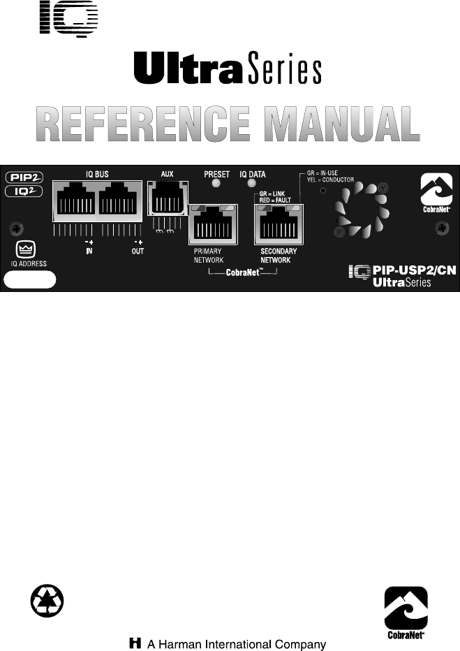
IQ-PIP-USP2/CN Figure 1.1 IQ-PIP-USP2/CN Front Panel 1 Welcome The IQ-PIP-USP2/CN is a PIP™ (Programmable Input Processor) input module for Crown® PIP2™-compatible amplifiers.* It connects the amplifier to the IQ Bus of an IQ System®, allowing the amplifier to be controlled and monitored via IQ, and features CobraNet™ connectivity for digital audio networking. The IQ-PIP-USP2/CN is an IQ2™series component.
IQ-PIP-USP2/CN 1.1 Unpacking The unit is shipped in a protective antistatic bag. CAUTION: STATIC ELECTRICITY MAY DAMAGE THE UNIT. Use caution when handling the unit. Carefully ground yourself BEFORE touching the unit. Avoid unnecessarily touching the components or solder pads on the circuit boards. Please unpack and inspect the unit for any damage that may have oc- IQ-PIP-USP2/CN Reference Manual curred during transit. If damage is found, notify the transportation company immediately.
IQ-PIP-USP2/CN 2 Controls, Connectors & Indicators Figure 2.
IQ-PIP-USP2/CN 3 Installation Before beginning, please carefully note: CAUTION: STATIC ELECTRICITY MAY DAMAGE THE IQ-PIP-USP2/CN MODULE. Use caution when handling the unit. Carefully ground yourself BEFORE touching the IQ-PIPUSP2/CN module. Avoid unnecessarily touching the components or solder pads on the circuit boards. 3.1 Prepare the PIP 1. Set the IQ address switch S1.. By giving each IQ component a unique address, it can be individually controlled and monitored.
IQ-PIP-USP2/CN reserved for special use. An address of “0” (zero) places the unit in “stand alone” mode. This special mode disables the IQ bus port, preventing communication with the IQ System. 3.2 Prepare the Amplifier 3. Turn down the level controls (full counterclockwise) and turn off the amplifier. 4. Disconnect the amplifier’s power cord. 5. Remove the existing PIP from the amplifier back panel (two screws). This may involve disconnecting the PIP from a PIP2 input adapter.
IQ-PIP-USP2/CN Both ribbon cables should run smoothly from the amplifier to the PIP card (see Figure 3.2). Important: Be careful when attaching the ribbon cable to the connector that the cable is properly seated before applying pressure to the connector. Forcing the cable onto the connector could cause the keying tabs, which ensure proper pin alignment, to break. Connecting the ribbon cables with improper pin alignments may result in damage to the PIP.
IQ-PIP-USP2/CN Figure 3.4 RJ-45 Mating Plug The following examples show how to connect the IQ-PIP-USP2/CN to other IQ components: Figure 3.5 RJ-45 Output to Barrier Block Input. Figure 3.6 RJ-45 Output to Din Input.
IQ-PIP-USP2/CN Figure 3.7 RJ-45 Input to Barrier Block Output. Figure 3.8 RJ-45 Input to Din Output. Figure 3.9 RJ-45 Output to RJ-45 Input.
IQ-PIP-USP2/CN 10. Connect the CobraNet network to the IQ-PIP-USP2/CN. Connect the primary network hub or switch to the primary network port on the PIP using high-grade UTP Cat-5 and “best” wiring practices for best results. For compliance with emission regulations, one of the supplied ferrite cores must be placed on the cable, with the cable making two passes through the core (see Figure 3.10).* Good network design and wiring practices are essential for reliable system operation. 11.
IQ-PIP-USP2/CN 4 Hardware Features This section describes the IQ-PIPUSP2/CN hardware features. These features are accessed via controls located on the unit itself. 4.1 IQ Address Switch (S1) An 8-section DIP switch is used to set the IQ address of the unit. A valid IQ address is any number from 1 to 250. Numbers higher than 250 are reserved for special use. An address of “0” places the unit in standalone mode. In this mode, the IQ bus port is disabled and the PIP will not function with IQ software.
IQ-PIP-USP2/CN 4.3 Data Indicator An amber Data Indicator (IQ DATA) is provided on the front panel (see Figure 4.1). It flashes whenever commands addressed to the IQ-PIPUSP2/CN are received. To assist with troubleshooting, an option that forces the DATA indicator to remain lit is available through IQ software. 4.4 Preset Indicator A green PRESET indicator is provided on the front panel (see Figure 4.1).
IQ-PIP-USP2/CN few seconds. The port is implemented as a standard 100Base-T Fast-Ethernet interface and should be wired with standard UTP Cat-5 or better cabling. the AUX Output is described in Section 9.3, and AUX Input operation is described in Secton 9.4. 4.10 AUX Input/Output Connector A “Drop out” relay is provided on the IQ Bus ports to maintain the continuity of the IQ communication loop even if the IQ-PIP-USP2/CN loses power.
IQ-PIP-USP2/CN 5 Amplifier Control and Monitoring This section describes the IQ-PIP-USP2/CN amplifier control and monitoring features. These features are accessed via IQ for Windows software. Please refer to the IQ for Windows documentation if you are unfamiliar with IQ software. 5.1 IOC Event Monitor The Input/Output Comparator (IOC®) of each channel of the amplifier can be monitored by the IQ System.
IQ-PIP-USP2/CN 5.5 Power/Standby Control Each channel’s high-voltage supply can be independently turned on and off. 5.6 Amp Information Several useful items of information about the host amplifier are determined by the IQ-PIP-USP2/CN at start-up. These include manufacturer, model, date code, serial number, and revision level. These can be printed from the system inventory (no on-screen display is available). 5.
IQ-PIP-USP2/CN when an amplifier “fault” condition occurs when a channel fails. PIP2compatible devices monitor a “fault” signal from the amplifier. Load: You can choose to be warned Page 22 if the impedance of the load being driven by the amplifier falls out of a pre-selected range. See Section 8 for instructions on setting up the load supervision feature.
IQ-PIP-USP2/CN 6 CobraNet CobraNet is a licensed technology developed by Peak Audio, Inc. consisting of proprietary communications protocol, firmware and hardware. It allows reliable, deterministic transmission of digital audio over a 100Base-T Fast-Ethernet network. The IQ-PIP-USP2/CN operates as a networked device on a CobraNet network, and interfaces digital audio from the network to the amplifer. Refer to Section 10.4 for a more thorough discussion about CobraNet technology.
IQ-PIP-USP2/CN 6.1.4 System Location This parameter is user-settable to any alpha-numeric string of 30 characters or less. The intended use is to communicate a unique description of the device location to a network. This object is stored in presets. 6.1.5 System Contact This parameter is user-settable to any alpha-numeric string of 30 characters or less. The intended use is to communicate the designated contact person (in case of service or other network issue) to the network.
IQ-PIP-USP2/CN mit Bundle includes the following controls and monitor functions: • Receiver Count: This meter reports the number of CobraNet nodes actively receiving the Bundle being sourced to the network by this bundle. • Transmit Position: This meter reports the transmitter’s relative position as assigned by the CobraNet Conductor. Lower numbers are transmitted before higher numbers. • Transmit Priority: This control adjusts the relative priority for the particular transmitter.
IQ-PIP-USP2/CN 7 Signal Processing This section describes the IQ-PIP-USP2/CN DSP signal processing features. These features are accessed via IQ for Windows software. Please refer to the IQ for Windows documentation if you are unfamiliar with IQ software. 7.1 Signal Processing Forms Many of the advanced features of the IQ-PIP-USP2/CN are accessed from the IQ for Windows software Signal Path panel.
IQ-PIP-USP2/CN signal level. Each attenuator has a range from 0 dB to –80 dB in ½ dB steps. (Zero equals no attenuation.) 7.5 Input Signal Compressor/Limiter 7.4 Auto Standby An input signal compressor/limiter is available for each channel. Five parameters control this feature: The Auto Standby feature automatically turns off the high-voltage supplies of the amplifier output when no audio signal is detected at the input for a predetermined period of time. The channels are controlled independently.
IQ-PIP-USP2/CN actual number depends on the mix of filters chosen). There are seven different filter types from which to choose. Low-Pass Crossover Filter (1st– 4th order) High-Pass Crossover Filter (1st– 4th order) Parametric Equalization Filter (2nd order only) Low-Pass Equalization Filter (2nd order only) High-Pass Equalization Filter (2nd order only) An indicator in the software shows how much DSP resources are being used by the selected filters.
IQ-PIP-USP2/CN 7.6.2 High-Pass Crossover Filter and the better the transient response and visa versa. 7.6.4 Low-Pass Equalization Filter Description: This filter rolls off low frequencies at a rate determined by the shape parameter. The filter is commonly used to feed the high frequency portion of an audio signal to horns or tweeters. It can be combined with a low-pass crossover filter to create a band-pass crossover filter for driving mid-range drivers. • Passband gain: Fixed at unity.
IQ-PIP-USP2/CN • Frequency: Sets the center frequency of the filter. The range is 20 Hz to 20 kHz. • Q: Sets the width, slope and gain of the filter. The range is 0.1 to 34. The lower the Q, the wider the filter, the lower the gain and the better the transient response and visa versa. Gain examples: A Q of 2 will result in 6 dB of gain at the center frequency and a Q of 4 will result in 12 dB of gain. 7.6.
IQ-PIP-USP2/CN 7.8.1 On/Off Turns the limiter on or off. connected to the respective channel. 7.8.2 Attack 7.9.4 Attack Time Attack time is adjustable from 10 milliseconds to 1 second per 10 dB of overdrive. Adjustable from 1 second to 30 seconds in 1 second increments. 7.8.3 Release Adjustable from 1 second to 30 seconds in 1 second increments. Release rate is adjustable from 100 milliseconds to 10 seconds per 10 dB or release. 7.8.
IQ-PIP-USP2/CN 7.13 Output Trim Controls 7.15 Tie Switch An output trim control is provided for each channel to adjust the output gain after processing, allowing for “make-up” gain to compensate for losses due to crossovers, etc. Range is +12 dB to –80 dB in ½-dB steps. The Tie switch connects all active compressors and limiters together so that any limiting/compression affects the signal on both channels, such as would typically be desired when processing stereo signals. 7.14 Polarity Inverter 7.
IQ-PIP-USP2/CN 8 Load Supervision This section describes the IQ-PIP-USP2/CN Load Supervision features. These features are accessed via IQ for Windows software. Please refer to the IQ for Windows documentation if you are unfamiliar with IQ software. The Load Supervision feature allows real time monitoring of the load connected to each amplifier channel. When enabled, the IQ-PIP-USP2/ CN continuously monitors the amplifier output voltage and current and calculates the long-term average load impedance.
IQ-PIP-USP2/CN 9 Utilities 9.3 AUX Output This section describes the IQ-PIP-USP2/CN Utility features. Some of these features are accessed via IQ for Windows software. Please refer to the IQ for Windows documentation if you are unfamiliar with IQ software. The AUX Output delivers 15 VDC at 10 mA maximum output when switched to logic High, and may be controlled via software or may be programmed to switch when a fail condition is present on any channel.
IQ-PIP-USP2/CN ited to prevent Presets outside a set range from being selected.* The Min Preset and Max Preset settings allow minimum and maximum Preset values to be specified. In the event the AUX Input is engaged while the * Regardles of the state of the Min Preset and Max Preset settings, all Presets are available for selection within IQ for Windows software.
IQ-PIP-USP2/CN 10 Working With IQ This section provides additional information about the IQ System with special guides to aid in the installation and use of the IQ-PIP-USP2/CN. For more information about any of these topics, contact the Crown Technical Support Group. 10.1 A Closer Look at IQ An IQ System is a computerized system which uses the IQ command protocol to control and monitor system functions.
IQ-PIP-USP2/CN 10.1.2 IQ2 Protocol (UCode) IQ2 is an advanced type of IQ command protocol developed primarily to allow third party IQ manufacturers to more quickly and easily produce compatible products that do not require intense software programming. Components that are designed with or are otherwise compatible with UCode protocol carry the IQ2 logo. use of the TCP/IP protocol services built into Windows and can run over any network that can be configured under Windows.* 10.1.
IQ-PIP-USP2/CN 10.2 IQ-PIP-USP2/CN User Interface Please note: It is assumed the reader has a basic familiarity with IQ for Windows. For more information about IQ for Windows, see the online documentation that accompanies the program, or visit the IQ website at www.iqaudiosystems.com. The IQ-PIP-USP2/CN GUI (Graphic User Interface), called the Control Panel, provides access to all available features.
IQ-PIP-USP2/CN Figure 10.2 General Control Tab 10.2.1 General Control Tab The General Control Tab contains controls common to most Crown PIPs. These include Stereo/Mono Switching, Model Selection, Amplifier Serial Number, Date Code, User Labels, Access to “All” commands, 8/4 Ohm - 70 volt switching for Crown Com-Tech “02” amplifiers, AUX Input Controls for polarity, mode, min preset and max preset and Firmware Program Version number. Figure 10.2 shows the General Control Tab.
IQ-PIP-USP2/CN Figure 10.3 Presets Control Tab 10.2.2 Presets Control Tab The Presets Control Tab allows you to store and recall PIP settings as Presets within the IQ-PIP-USP2/CN and assign each Preset a name (see Section 9.1 for information about Presets). Checking the “Prompt to recall or store” checkbox causes a prompt to be issued whenever a Preset button is pressed. The prompt gives you the choice of Recalling the Preset, Storing the Preset or Cancel.
IQ-PIP-USP2/CN Figure 10.4 Error Reporting Control Tab 10.2.3 Error Reporting Tab The Error Reporting Control Tab contains controls which can be used to set the conditions under which error notices are triggered (see Section 5.9 for information about Error Reporting). When an error is triggered under one of these conditions, an error alert is generated. IQ for Windows can generate alerts such as: dialog box on screen, fax, e-mail, play wave file, etc.
IQ-PIP-USP2/CN Figure 10.5 Load Supervision Control Tab 10.2.4 Load Supervision Control Tab The Load Supervision Control Tab contains load supervision controls and test result indicators for each channel of an amplifier (see Section 8 for information about Load Supervision). Load supervision allows you Page 42 monitor the average impedance of your amplifier’s load, and alerts you if it falls outside of set limits. Figure 10.5 shows the Load Supervision Control Tab.
IQ-PIP-USP2/CN Figure 10.6 Signal Path Control Tab 10.2.5 Signal Path Control Tab The Signal Path Control Tab allows setup and control of all the audio signal path functions available in the chosen signal processing form (see Section 7.1 for information about signal processing forms).
IQ-PIP-USP2/CN Figure 10.7 CobraNet Setup Control Tab 10.2.6 CobraNet Setup Control Tab The CobraNet Setup Control Tab provides access to the CobraNet module control and monitoring features. System identificaton and addressing, Conductor priority, and status and error indicators are all Page 44 available within this tab (see Section 6.1 for information about the CobraNet module). Figure 10.7 shows the CobraNet Setup Control Tab.
IQ-PIP-USP2/CN Figure 10.8 CobraNet Input Control Tab Figure 10.9 CobraNet Output Control Tab 10.2.7 CobraNet Input and Output Control Tabs The CobraNet Input and Output Control Tabs provide access to the CobraNet Network,and make it easy to route CobraNet audio into and out of the IQ-PIP-USP2/CN (see Section 6 for more information about CobraNet).
IQ-PIP-USP2/CN 10.3 IQ Bus Wiring The IQ-PIP-USP2/CN must be connected to a IQ Bus loop having an IQ2-compatible IQ interface in order for the IQ System to control or monitor it. The IQ Bus is a serial communication loop designed to transmit IQ commands and data. As implemented in the IQ-PIP-USP2/ CN, it is a 20 milliamp current loop operating at a BAUD rate of 38.4 K. The loop must be unbroken to function properly.
IQ-PIP-USP2/CN Lower capacitance allows longer loops. Unshielded wire usually has less capacitance. • Never use the ground wire in a mic snake line. It may sometimes be convenient to run IQ Bus data signals to and from stage monitor amplifiers along unused wire pairs in a mic snake. Do not use the ground wire which is normally connected to pin 1 on an XLR connector or data noise will be added to the audio lines. Use only the signal lines which normally connect to pins 2 and 3 of the XLRs.
IQ-PIP-USP2/CN Figure 10.11 Multi-Star Topology In larger Fast Ethernet networks, additional hubs, concentrators, and other network hardware are used to form a larger network, as shown in Figure 10.11. fixed at 256 samples yielding a network transmission latency of 5.333 ms (256 samples at 1/48 kHz per sample). Today, commonly available networking cards are 10/100Base-T capable, which allows them to be used on either 10BaseT or 100Base-T networks.
IQ-PIP-USP2/CN ing information. The “beat” also includes information as to which addresses can transmit at certain time slots within the “beat” period. The Conductor regulates the CobraNet digital audio traffic on the CobraNet network. Each transmitter is given a “permission” to transmit in a given time-slot within the Conductor controlled isochronous cycletime. The time-slot is determined by the assigned bundle priority. Higher bundle priorities receive lower-numbered positions and are transmitted first.
IQ-PIP-USP2/CN network must be dedicated to CobraNet traffic only to guarantee reliable transmission of audio packets. 10.4.6 Switched Networks A more complex CobraNet network can be built using Ethernet Switches.* Ethernet switching technology is more sophisticated than hubs. Switches do not simply broadcast each and every packet to all nodes. Instead, they can interrogate each incoming packet transmission to determine its destination and (very quickly) transmit the data to only that destination port.
IQ-PIP-USP2/CN 10.5.1 AUX Output The AUX Output feature provides either 0 or +15 VDC across pins 3 (ground) and 4 (+) when the feature is turned on by IQ for Windows software, depending on whether the polarity is set to inverting or noninverting (see Section 9.4). A total of 10 milliamps of current is available. A 1.8 K ohm resistor protects against shorts (See Figure 10.12). There are many possible uses for the AUX Output. For example, it can be used to turn on auxiliary cooling fans.
IQ-PIP-USP2/CN 10.5.2 AUX Input Figure 10.13 A Sample AUX Output Circuit The AUX connector can be used to sense the presence of an input signal across pins 2 (+) and 5 (ground). Like the AUX Output, the AUX Input polarity can be set to either inverting or non-inverting. When set to non-inverting, a +5 to +35 VDC signal at the input is interpreted as a logic “high” and a signal less than +1.6 VDC is interpreted as a logic “low.
IQ-PIP-USP2/CN optimizes the supervision algorithm for voltage and current levels versus the actual load. Note: a higher nominal setting will require higher output levels. 5. Set the high limit at twice average and the low limit at one-fourth nominal.* 6. Let the system run for extended periods using any and all typical program material. 7. Adjust the high/low limits, if necessary, to account for any variance in average measured impedance. 8. Enable error reporting, if desired.
IQ-PIP-USP2/CN that the algorithm simply cannot overcome. In these cases, widening the high and low limits will help de- crease the “sensitivity” of supervision and decrease chance of “nuisance” error reports. 10.7 Q-Factor Calculation width in octaves. The table relates the Q-factor to bandwidth in octaves according to the equation: Many of the DSP filters on the IQPIP-USP2/CN feature adjustable Qfactor, which is a measure of the filter’s selectivity or sharpness.
IQ-PIP-USP2/CN 10.8 Working with RJ-11 and RJ-45 Connectors Pin assignments for standard RJ-11 and RJ-45 connectors are indicated in Figure 10.15. RJ-11 RJ-45 Figure 10.15 RJ-11 & RJ-45 Pin Assignments When wiring RJ-11 connectors, it is good practice to follow the USOC protocol for RJ-11 connector cable.
IQ-PIP-USP2/CN Figure 10.
IQ-PIP-USP2/CN Figure 10.
IQ-PIP-USP2/CN Figure 10.
IQ-PIP-USP2/CN Figure 10.19 IQ-PIP-USP2/CN Signal Flow Block Diagram 10.
IQ-PIP-USP2/CN 11 Specifications 11.1 General Internal Controls: An 8-segment DIP switch sets the IQ address (decimal range: 1–250).* A Reset/Preset switch, accessible with a straightened paper clip through the PIP panel, selects the next user preset if pressed for less than 2 seconds, resets the PIP to preset “0” if pressed for more than 2 seconds, or restores all settings and presets to factory default if pressed while applying power.
IQ-PIP-USP2/CN or larger. Can be extended with an IQ Repeater. Distortion: Less than 0.05% THD+N, 20 Hz to 20 kHz (referenced to 1 kHz, 0 dBu input signal). 11.3 Audio Crosstalk: better than –80 dB, fullscale input level, 20 Hz to 20 kHz input frequency sweep, 20 Hz to 20 kHz bandwidth. Please note: The audio specifications are referenced to 0.775 V (0 dBu). Measurements were made at the output of the IQ-PIP-USP2/CN module.
IQ-PIP-USP2/CN 12 Factory Service To obtain factory service, fill out the service information page found in the back of this manual and send it along with your proof of purchase and the defective unit to the Crown factory. For warranty service, we will pay for ground shipping both ways in the United States. Contact Crown Factory Service or Technical Support to obtain prepaid shipping labels prior to sending the unit. Or, if you prefer, you may prepay the cost of shipping, and Crown will reimburse you.
3 YEAR NORTH AMERICA SUMMARY OF WARRANTY The Crown Audio Division of Crown International, Inc., 1718 West Mishawaka Road, Elkhart, Indiana 46517-4095 U.S.A. warrants to you, the ORIGINAL PURCHASER and ANY SUBSEQUENT OWNER of each NEW Crown product, for a period of three (3) years from the date of purchase by the original purchaser (the “warranty period”) that the new Crown product is free of defects in materials and workmanship.
WORLDWIDE SUMMARY OF WARRANTY The Crown Audio Division of Crown International, Inc., 1718 West Mishawaka Road, Elkhart, Indiana 46517-4095 U.S.A.
Crown Factory Service Information Shipping Address: Crown Factory Service, Plant 2 SW, 1718 W. Mishawaka Rd., Elkhart, IN U.S.A.