Macro-Tech 02 Series Macro-Tech 602, 1202 & 2402 Operation Manual Obtaining Other Language Versions: To obtain information in another language about the use of this product, please contact your local Crown Distributor. If you need assistance locating your local distributor, please contact Crown at 574-294-8000. This manual does not include all of the details of design, production, or variations of the equipment.
MA Series Power Amplifiers Important Safety Instructions 1) 2) 3) 4) 5) 6) 7) 8) 9) 10) 11) 12) 13) 14) 15) page 2 Read these instructions. Keep these instructions. Heed all warnings. Follow all instructions. Do not use this apparatus near water. Clean only with a dry cloth. Do not block any ventilation openings. Install in accordance with the manufacturer’s instructions. Do not install near any heat sources such as radiators, heat registers, stoves, or other apparatus that produce heat.
MA Series Power Amplifiers DECLARATION of CONFORMITY Crown International, Inc. TCF Technical Certificate No: P4300CRI1.IWS Technical Construction File Route Issued By: Crown International, Inc. 1718 W. Mishawaka Road Elkhart, Indiana 46517 U.S.A.
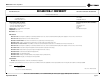
MA Series Power Amplifiers Table of Contents Important Safety Instructions .......................... 2 5.1.2 Standby Mode .................................... 14 Declaration of Conformity ................................ 3 5.1.3 Transformer Thermal Protection ......... 14 1 Welcome ................................................... 5 5.1.4 Fuses and Circuit Breakers ................. 15 1.1 Features .............................................. 5 5.2 Advanced Features ............................
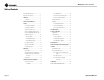
MA Series Power Amplifiers MA-602 *1 kHz **20 Hz–20 kHz Power Power 2 ohm Dual (per ch.) 400W 335W 4 ohm Dual (per ch.) 325W 300W 8 ohm Dual (per ch.) 225W 210W 4 ohm Bridge-Mono 750W 650W 8 ohm Bridge-Mono 655W 605W *1 kHz Power: refers to maximum average power in watts at 1 kHz with 0.1% THD. **20 Hz–20 kHz Power: refers to maximum average power in watts from 20 Hz to 20 kHz with 0.1% THD. MA-1202 *1 kHz **20 Hz–20 kHz Power Power 2 ohm Dual (per ch.) 675W 585W 4 ohm Dual (per ch.
MA Series Power Amplifiers page 6 Operation Manual
MA Series Power Amplifiers 3 Setup 3.4 Choose Input Wire and Connectors Crown recommends using pre-built or professionally wired, balanced line (two-conductor plus shield), 22-24 gauge cables and connectors.The factory-installed PIP2-FXQ input module accepts 3-pin male XLR connectors or TRS phone connectors. Other PIP modules accept XLR, phone or Phoenix connectors, or bare wires. Regarding the PIP2-FXQ, Figure 3.3 shows connector pin assignments for balanced wiring, and Figure 3.
MA Series Power Amplifiers 3 Setup 3.6 Wire Your System Turn down the Level controls (fully counterclockwise) and turn off the amplifier before wiring it as described below. 3.6.1 Stereo Mode See Figure 3.6. Set the back panel stereo/mono switch to Stereo. Figure 3.6 Stereo Wiring INPUTS: Connect input wiring to both channels. OUTPUTS: Maintain proper polarity (+/-) on output connectors. Connect Channel 1 positive (+) speaker load to Channel 1 positive terminal of amp; repeat for negative (-).
MA Series Power Amplifiers 3 Setup 3.6.3 Parallel-Mono Mode See Figure 3.8. Set the back panel stereo/mono switch to Parallel-Mono. INPUTS: Connect input wiring to Channel 1 only. OUTPUTS: Add a 14 gauge (or larger) jumper between the red(+) Channel 1 and Channel 2 binding posts. Connect the speaker positive (+) lead to the Channel 1 red (+) terminal. Connect the speaker negative (-) lead to the Channel 1 black (-) terminal.
MA Series Power Amplifiers 3.7 Set Input Sensitivity The input sensitivity switch inside the amplifier is set to 0.775 volt RMS at the factory. (Factory setting for international models is 1.4V). It can be changed to 1.4 volts or a voltage gain of 26 dB. The 26 dB gain setting is equivalent to a sensitivity of 2.2 volts for the Macro-Tech 602, 2.6 volts for the Macro-Tech 1202 and 3.1 volts for the Macro-Tech 2402. To change the input sensitivity: 1. Turn off and unplug the amplifier from the AC source. 2.
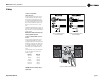
MA Series Power Amplifiers 4 Operation 4.2 Front Panel Controls and Indicators The diagram below shows the controls and indicators on the front panel of the Macro-Tech 02 Series. A. Dust Filters The dust filters remove large particles from the air drawn in by the cooling fan. Check the filters regularly to prevent clogging. The filter elements can be easily removed for cleaning by gently pulling them away from the front panel. B.
MA Series Power Amplifiers 4 Operation 4.3 Back Panel Controls, Indicators and Connectors G. Power Cord The power cord has an appropriate plug for the required voltage. 120 VAC, 60 Hz North American Macro-Tech 602s and 1202s have 14 AWG line cords and NEMA 515P plugs. Macro-Tech 2402s have 12 AWG line cords and NEMA 5-20P plugs. International units are shipped with an appropriate line cord and plug. See Section 7 for AC power usage. H.
MA Series Power Amplifiers 4 Operation 4.4 Indicators The amber Enable indicator is provided to show that the amplifier has been turned on (or enabled), and that its low-voltage power supply and forced-air cooling system are working. It does not indicate the status of the high-voltage power supplies. For example, the Enable indicator will remain lit during unusual conditions that would cause the amplifier's protection systems to put a high-voltage power supply in "standby" mode (see Section 5.1.2).
MA Series Power Amplifiers 5 Advanced Features and Options 5.1 Protection Systems Macro-Tech amplifiers provide extensive protection and diagnostics capabilities. Protection systems include ODEP, "standby" mode, fuses (or breakers), and special thermal protection for the unit's transformers. 5.1.1 ODEP Crown invented ODEP to solve two long-standing problems in amplifier design: to prevent amplifier shutdown during demanding operation and to increase the efficiency of the output circuitry.
MA Series Power Amplifiers 5 Advanced Features and Options 5.1.4 Fuses and Circuit Breakers The power supplies of the Macro-Tech 602 and 1202 are protected by fuses. The power supplies of the Macro-Tech 2402 are protected by circuit breakers. With rated loads and output levels, the fuses (or circuit breakers) should only shut down the amplifier in the rare instance of a catastrophic failure. Other protection systems like ODEP keep the amplifier operational under most other severe conditions.
MA Series Power Amplifiers 5 Advanced Features and Options 5.3 Options 5.3.1 PIP and PIP2 Modules Versatile PIP (Programmable Input Processor) modules provide flexible expansion features that can be added to customize the amplifier. PIP modules plug into the connector inside the back panel of the amplifier. PIP modules are available with a features ranging from errordriven compressor/limiters to IQ control.
MA Series Power Amplifiers For PIP2s featuring ribbon cable connectors, simply locate the two connectors on the underside of the PIP circuit board, then connect the two input ribbon cables coming from the amplifier (see Figure 5.3). Both ribbon cables should run smoothly from the amplifier to the PIP card. Insert the PIP and attached cables into the PIP opening in the back of the amplfier, then screw securely into place. WARNING: Disconnect power to the amplifier when installing or removing a PIP module.
MA Series Power Amplifiers 6 Troubleshooting Indicator Status The table in Figure 6.1 shows the possible states for the ODEP and Signal/IOC indicators. It also describes the conditions that may be associated with the different indicator states. The Enable indicator will be off with the first indicator state, "There is no power to the amplifier." All other conditions in the table will occur with the Enable indicator turned on.
MA Series Power Amplifiers 7 Theory of Operation 7.1 Overview Your Macro-Tech amplifier incorporates several advanced technological features including realtime computer simulation of output transistor stress, low-stress output stages, an advanced heat sink embodiment and the PIP2 (Programmable Input Processor) expansion system. Custom circuitry is incorporated to limit temperature and current to safe levels, making it highly reliable and tolerant of faults.
MA Series Power Amplifiers 7 Theory of Operation The bridge-balanced circuit (U104-B) receives a signal from the output of the amplifier, and differences it with the signal at the Vcc supply. The bridge-balanced circuit then develops a voltage to drive the bridge-balanced output stage. This results in the Vcc supply having exactly one half of the output voltage added to their quiescent voltage. D309, D310, D311 and a trimmer resistor set the quiescent current point for the bridge-balanced output stage.
MA Series Power Amplifiers 8 Specifications Minimum Guaranteed Power Macro-Tech 602 Macro-Tech 1202 Macro-Tech 2402 120 VAC, 60 Hz Units, Stereo mode, per channel, both channels driven 1 kHz with 0.1% THD Stereo, 2 ohms per ch. Stereo, 4 ohms per ch. Stereo, 8 ohms per ch.
MA Series Power Amplifiers 8 Specifications Performance (continued) Macro-Tech 602 Macro-Tech 1202 Macro-Tech 2402 2-8 ohms 4-16 ohms 1-4 ohms 2-8 ohms 4-16 ohms 1-4 ohms 2-8 ohms 4-16 ohms 1-4 ohms 35 dB ± 0.5 dB 30 dB ± 0.5 dB 26 dB 36 dB ± 0.5 dB 31 dB ± 0.5 dB 26 dB 38 dB ± 0.5 dB 33 dB ± 0.
MA Series Power Amplifiers 8 Specifications Figure 8.
MA Series Power Amplifiers 8 Specifications Figure 8.
MA Series Power Amplifiers 8 Specifications Figure 8.
MA Series Power Amplifiers 8 Specifications Figure 8.
MA Series Power Amplifiers 8 Specifications Figure 8.
MA Series Power Amplifiers 8 Specifications Figure 8.
MA Series Power Amplifiers 9 AC Power Draw andThermal Dissipation This section provides detailed information about the amount of power and current drawn from the AC mains by Macro-Tech 602, 1202 and 2402 amplifiers and the amount of heat produced under various conditions. The calculations presented here are intended to provide a realistic and reliable depiction of the amplifiers.
MA Series Power Amplifiers 9 AC Power Draw and Thermal Dissipation Figure 9.1 Macro-Tech 602 Power Draw, Current Draw and Thermal Dissipation at Various Duty Cycles Figure 9.2 Macro-Tech 1202 Power Draw, Current Draw and Thermal Dissipation at Various Duty Cycles Figure 9.
MA Series Power Amplifiers 10 Service Crown amplifiers are quality units that rarely require servicing. Before returning your unit for servicing, please contact Crown Factory Service to verify the need for servicing. This unit has very sophisticated circuitry which should only be serviced by a fully trained technician. This is one reason why each unit bears the following label: CAUTION: To prevent electric shock, do not remove covers. No user serviceable parts inside.
MA Series Power Amplifiers 11 Warranty UNITED STATES & CANADA SUMMARY OF WARRANTY 3 AR YE Crown International, 1718 West Mishawaka Road, Elkhart, Indiana 46517-4095 U.S.A. warrants to you, the ORIGINAL PURCHASER and ANY SUBSEQUENT OWNER of each NEW Crown product, for a period of three (3) years from the date of purchase by the original purchaser (the “warranty period”) that the new Crown product is free of defects in materials and workmanship.
MA Series Power Amplifiers 11 Warranty WORLDWIDE EXCEPT USA & CANADA of the reason for failure, except as excluded in this Warranty. 3 AR YE 1 Note: If your unit bears the name “Amcron,” please substitute it for the name “Crown” in this warranty. ITEMS EXCLUDED FROM THIS CROWNWARRANTY This Crown Warranty is in effect only for failure of a new Crown product which occurred within the Warranty Period.
MA Series Power Amplifiers NOTES page 34 Operation Manual
MA Series Power Amplifiers Crown Factory Service Information Shipping Address: Crown Factory Service, 1718 W. Mishawaka Rd.