Models: Macro-Tech 600, 1200 & 2400 Macro-Tech 601, 1201 & 2401 Some models may be exported under the name Amcron®. ©2003 by Crown Audiol, Inc., P.O. Box 1000, Elkhart, IN 46515-1000 U.S.A. Telephone: 574-294-8000. Fax: 574-294-8329. Trademark Notice: SmartAmp, PIP and Grounded Bridge are trademarks and Amcron, Crown, Macro-Tech, IOC, ODEP, IQ System, and P.I.P. are registered trademarks of Crown International, Inc. Other trademarks are the property of their respective owners.
3 YEAR THREE YEAR FULL WARRANTY 3 YEAR WORLDWIDE NORTH AMERICA SUMMARY OF WARRANTY The Crown Audio Division of Crown International, Inc., 1718 West Mishawaka Road, Elkhart, Indiana 46517-4095 U.S.A.
The information furnished in this manual does not include all of the details of design, production, or variations of the equipment. Nor does it cover every possible situation which may arise during installation, operation or maintenance. If your unit bears the name “Amcron,” please substitute it for the name “Crown” in this manual. If you need special assistance beyond the scope of this manual, please contact our Technical Support Group. Crown Technical Support Group 1718 W. Mishawaka Rd.
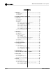
Macro-Tech 600/1200/2400 Power Amplifiers CONTENTS 1 Welcome ............................................................................ 7 1.1 Unpacking ................................................................... 7 1.2 Features ...................................................................... 7 2 Controls, Indicators & Connectors ................................... 8 3 Installation ....................................................................... 10 3.1 Mounting ........................
Macro-Tech 600/1200/2400 Power Amplifiers ILLUSTRATIONS 1.1 2.1 2.2 3.1 3.2 3.3 3.4 3.5 3.6 3.7 3.8 3.9 3.10 3.11 3.12 3.13 3.14 3.15 4.1 4.2 4.3 5.1 6.1 6.2 6.3 6.4 6.5 6.6 6.7 6.8 6.9 6.10 6.11 6.12 6.13 7.1 7.2 7.3 8.1 8.2 Reference Manual Macro-Tech Amplifier ................................................................ 7 Front Panel Controls & Indicators .............................................. 8 Rear Panel Controls & Connectors ............................................
Macro-Tech 600/1200/2400 Power Amplifiers Important Safety Instructions 1) Read these instructions. 2) Keep these instructions. 3) Heed all warnings. 4) Follow all instructions. 5) Do not use this apparatus near water. 6) Clean only with a damp cloth. 7) Do not block any of the ventilation openings. Install in accordance with the manufacturer’s instructions. 8) Do not install near any heat sources such as radiators, heat registers, stoves, or other apparatus that produce heat.
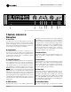
Macro-Tech 600/1200/2400 Power Amplifiers Fig. 1.1 Macro-Tech Amplifier 1 Welcome Congratulations on your purchase of the renowned Macro-Tech® professional power amplifier. Macro-Tech amplifiers are designed to provide enormous levels of pure, undistorted power in a rugged low-profile package—making them the choice for pro sound reinforcement. They utilize our patented ODEP® protection circuitry to keep the show going long after other amplifiers have shut down.
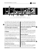
Macro-Tech 600/1200/2400 Power Amplifiers Fig. 2.1 Front Panel Controls & Indicators 2 Controls, Indicators & Connectors A. Dust Filters The dust filters remove large particles from the air drawn in by the cooling fan. Check the filters regularly to prevent clogging. The filter elements can be easily removed for cleaning by gently pulling them away from the front panel (see Sections 3.2 and 4.5). B.
Macro-Tech 600/1200/2400 Power Amplifiers Fig. 2.2 Rear Panel Controls & Connectors (Note: Reset Switches (Item I) only available on the Macro-Tech 2400 model.) are controlled by this switch. Stereo mode is used for normal two-channel operation, Bridge-Mono mode is used to drive a single channel with a load impedance of at least 4 ohms, and Parallel-Mono mode is used to drive a single channel with an impedance less than 4 ohms.
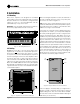
Macro-Tech 600/1200/2400 Power Amplifiers 3 Installation 3.1 Mounting Macro-Tech amplifiers are designed for standard 19-inch (48.3-cm) rack mounting and “stack” mounting without a cabinet. For more efficient cooling and extra support in a rack, it is recommended that units be stacked directly on top of each other. Important: If the unit will be transported, it should also be securely supported at the back of the rack.
Macro-Tech 600/1200/2400 Power Amplifiers 3.3 Wiring This section describes the most common ways to install your amplifier in a sound system. The input and output terminals are located on the back panel. Please use care when making connections, selecting signal sources and controlling the output level. The load you save may be your own! Crown assumes no liability for damaged loads resulting from careless amplifier use or deliberate overpowering.
Macro-Tech 600/1200/2400 Power Amplifiers 3.3.2 Bridge-Mono Operation Bridge-Mono mode is intended for driving loads with a total impedance of 4 ohms or more (If the load is less than 4 ohms, see Section 3.3.3). Installing the amplifier in Bridge-Mono mode is very different from the other modes and requires special attention. To put the amplifier in Bridge-Mono mode, turn the amplifier off and slide the stereo/mono switch to the right (as you face the back of the amplifier).
Macro-Tech 600/1200/2400 Power Amplifiers 3.3.3 Parallel-Mono Operation Parallel-Mono mode is intended for driving loads with a net impedance of less than 4 ohms. (See Bridge-Mono if the load is 4 ohms or greater.) Installing the amp in Parallel-Mono mode is very different from the other modes and requires special attention. CAUTION: Do not attempt to operate in Stereo or Bridge-Mono mode until the Parallel-Mono jumper is first removed. Failure to do so will result in high distortion and excessive heating.
Macro-Tech 600/1200/2400 Power Amplifiers 3.3.4 Input Connection Both the balanced XLR and phone jack inputs have a nominal impedance of 20 k ohms (10 k ohms with unbalanced wiring) and will accept the line-level output of most devices. Female three-pin XLR input connectors are provided on the standard P.I.P.- FX input module (other PIP modules are described in Section 8.1).
Macro-Tech 600/1200/2400 Power Amplifiers 910 Ω SOLVING INPUT PROBLEMS Sometimes large infrasonic (subaudible) frequencies are present in the input signal. These can damage loudspeakers by overloading or overheating them. To attenuate such frequencies, place a capacitor in series with the input signal line. The graph in Figure 3.10 shows some capacitor values and how they affect the frequency response. Use only low-leakage paper, mylar or tantalum capacitors. + A + .
Macro-Tech 600/1200/2400 Power Amplifiers shielded pair cable is another effective way to reduce or eliminate hum resulting from inductive coupling. Ground loops often result when two or more devices are improperly grounded. This causes undesirable stray currents that may produce hum in the output. The best way to avoid ground loops is to ensure that all system devices are plugged into the same power strip. In addition, make sure that all cable shields are grounded at one end only. resistance increases.
Macro-Tech 600/1200/2400 Power Amplifiers 1. Note the load resistance of the loudspeakers connected to each channel of the amplifier. Mark this value on the “Load Resistance” line of the nomograph. 2. Select an acceptable damping factor and mark it on the “Damping Factor” line. Your amplifier can provide an excellent damping factor of 1,000 from 10 to 400 Hz in Stereo mode with an 8-ohm load. In contrast, typical damping factors are 50 or lower.
Macro-Tech 600/1200/2400 Power Amplifiers 3.3.6 Additional Load Protection Macro-Tech amplifiers generate enormous power. If your loudspeakers do not have built-in protection from excessive power, it’s a good idea to protect them. Loudspeakers are subject to thermal damage from sustained overpowering and mechanical damage from large transient voltages. Special fuses can be used to protect your loudspeakers in both cases.
Macro-Tech 600/1200/2400 Power Amplifiers 4 Operation 4.1 Precautions Macro-Tech amplifiers are protected from internal and external faults, but you should still take the follow precautions for optimum performance and safety: 1. Improper wiring for Stereo, Bridge-Mono and Parallel-Mono modes can result in serious operating difficulties. Refer to Section 3.3 for details. 2. WARNING: Do not change the position of the stereo/mono switch unless the amplifier is first turned off. 3.
Macro-Tech 600/1200/2400 Power Amplifiers The table in Figure 4.2 shows the possible states for the ODEP and Signal/IOC indicators. It also describes the conditions that may be associated with the different indicator states. The Enable indicator will be off with the first indicator state, “There is no power to the amplifier.” All other conditions in the table will occur with the En- able indicator turned on.
Macro-Tech 600/1200/2400 Power Amplifiers 4.3 Protection Systems Macro-Tech amplifiers provide extensive protection and diagnostics capabilities. Protection systems include ODEP, “standby” mode, fuses (or breakers), and special thermal protection for the unit’s transformers. 4.3.1 ODEP Crown invented ODEP to solve two long-standing problems in amplifier design: to prevent amplifier shutdown during demanding operation and to increase the efficiency of the output circuitry.
Macro-Tech 600/1200/2400 Power Amplifiers 4.3.4 Fuses and Circuit Breakers The power supplies of the Macro-Tech 600 and 1200 are protected by fuses. The power supplies of the Macro-Tech 2400 are protected by circuit breakers. With rated loads and output levels, the fuses (or circuit breakers) should only shut down the amplifier in the rare instance of a catastrophic failure. Other protection systems like ODEP keep the amplifier operational under most other severe conditions.
Macro-Tech 600/1200/2400 Power Amplifiers standard 1-kHz power, the middle position provides 26 dB gain, and the back position sets the sensitivity to 0.775 volts for standard 1-kHz power. 5. Replace the PIP module and reconnect the power to the amplifier. The Ground Lift switch is located on the back panel and can provide isolation between the input signal grounds and the AC (chassis) ground. It affects only the phone jack inputs and has no affect on the PIP module input connectors.
Macro-Tech 600/1200/2400 Power Amplifiers 5 Technical Information 5.1 Overview Your Macro-Tech amplifier incorporates several new technological advancements including real-time computer simulation of output transistor stress, low-stress output stages, an advanced heat sink embodiment and the Programmable Input Processor (PIP) expansion system. Custom circuitry is incorporated to limit temperature and current to safe levels, making it highly reliable and tolerant of faults.
Macro-Tech 600/1200/2400 Power Amplifiers Fig. 5.
Macro-Tech 600/1200/2400 Power Amplifiers The balanced gain stage (U104-C and U104-D) causes balanced to single-ended conversion using a difference amplifier. From there, gain can be controlled with a potentiometer. The error amp (U104-A) amplifies the difference between the output signal and the input signal from the gain pot, and drives the voltage translator stage.
Macro-Tech 600/1200/2400 Power Amplifiers 6 Specifications The following applies to units in Stereo mode with 8-ohm loads and an input sensitivity of 26 dB gain unless otherwise specified. Standard 1 kHz Power: refers to maximum average power in watts at 1 kHz with 0.1% THD. Full Bandwidth Power: refers to maximum average power in watts from 20 Hz to 20 kHz with 0.1% THD. 120 VAC, 60 Hz Units: refers to amplifiers with dedicated transformers for 120 VAC, 60 Hz power mains.
Macro-Tech 600/1200/2400 Power Amplifiers Stereo/Mono: A three-position back panel switch used to select Stereo, Bridge-Mono or Parallel-Mono mode. Sensitivity: A three-position switch inside the PIP compartment used to select the input sensitivity for both channels: 0.775 volts or 1.4 volts for standard 1 kHz power, or a 26 dB voltage gain. Ground Lift: A two-position back panel switch for isolating the phone jack input grounds from the AC ground.
Macro-Tech 600/1200/2400 Power Amplifiers Crown specifications are guaranteed for three years. In an effort to provide you with as much information as possible about the high power-producing capabilities of your amplifier, we have created the following power matrices. Minimum Guaranteed Power Specifications Crown’s minimum power specifications represent the absolute smallest amount of output power you can expect from your amplifier when it is driven to full output under the given conditions.
Macro-Tech 600/1200/2400 Power Amplifiers Fig. 6.2 Macro-Tech 1200 Minimum Power Matrix Fig. 6.
Macro-Tech 600/1200/2400 Power Amplifiers Maximum Power Specifications Crown’s maximum power specifications represent the largest amount of output power you can expect from your amplifier when it is driven to full output under the given conditions. These specifications can be used to prevent loudspeaker and hearing damage. The maximum power matrices include specifications for single cycle and 40 millisecond burst sine waves.
Macro-Tech 600/1200/2400 Power Amplifiers Fig. 6.5 Macro-Tech 1200 Maximum Power Matrix Fig. 6.
Macro-Tech 600/1200/2400 Power Amplifiers +2 +1 0 –1 –2 8 ohm 4 ohm –3 2 ohm 1 watt dB –4 –5 –6 –7 10 100 1K 10 K 100 K FREQUENCY (Hz) Fig. 6.7 Typical Frequency Response 1400 1200 1000 800 600 400 8 ohm 200 100 0 100 20 1K 10 K 20 K FREQUENCY (Hz) Fig. 6.8 Typical Damping Factor 504.0 126.8 6 dB MILLIOHMS 31.8 8.0 2.0 10 100 1K 10 K 100 K FREQUENCY (Hz) Fig. 6.
Macro-Tech 600/1200/2400 Power Amplifiers TEF Measurement +45˚ 0˚ –45˚ TEF ® 100 1K 10 K 20 K FREQUENCY (Hz) Fig. 6.10 Typical Phase Response TEF Measurement –51 –57 –63 dB –69 –75 –81 100 TEF ® 1K 10 K 20 K FREQUENCY (Hz) Fig. 6.
Macro-Tech 600/1200/2400 Power Amplifiers –66 TEF Measurement –72 –78 –84 dB –90 –96 –102 100 TEF ® 1K 10 K 20 K FREQUENCY (Hz) Fig. 6.12 Typical Crosstalk for the Macro-Tech 1200 –60 TEF Measurement –66 –72 –78 dB –84 –90 –96 100 TEF ® 1K 10 K 20 K FREQUENCY (Hz) Fig. 6.
Macro-Tech 600/1200/2400 Power Amplifiers 7 AC Power Draw and Thermal Dissipation This section provides detailed information about the amount of power and current drawn from the AC mains by the Macro-Tech 600, 1200 and 2400 amplifiers and the amount of heat produced under various conditions. The calculations presented here are intended to provide a realistic and reliable depiction of the amplifiers.
Macro-Tech 600/1200/2400 Power Amplifiers Fig. 7.2 Macro-Tech 1200 Power Draw, Current Draw and Thermal Dissipation at Various Duty Cycles Fig. 7.
Macro-Tech 600/1200/2400 Power Amplifiers 8 Accessories 8.1 PIP Modules One advantage of Macro-Tech amplifiers is the ability to customize them using PIP (Programmable Input Processor) and PIP2 modules. Macro-Tech amplifiers are equipped with an edge card connector inside the back panel PIP compartment. The modules install easily: L BACK PANE ER OF AMPLIFI P.I.P.®–FTE uses balanced 1:1 transformers to isolate the amplifier from the input signal.
Macro-Tech 600/1200/2400 Power Amplifiers p oe n a ir.t P.I.P.®–CLP detects and prevents overload. Its compressor is driven by the amplifier’s built-in IOC error detection circuitry. Unlike typical signal-driven compressors, it only compresses the signal to prevent overload. It can deliver up to 13 dB of additional headroom without being noticeable. ® P.I.P. –ATNB uses balanced 1:1 transformers to isolate the amplifier from the input signal.
Macro-Tech 600/1200/2400 Power Amplifiers 8.2 Cooling Fan Options Every Macro-Tech amplifier has a built-in high-velocity fan that provides optimum cooling. Two optional replacement fan blades are available for special cooling requirements. Crown part C 6594-3 is a quieter, lowvelocity fan blade that in many cases can provide adequate cooling.
Macro-Tech 600/1200/2400 Power Amplifiers 9 Service This unit has very sophisticated circuitry which should only be serviced by a fully trained technician. This is one reason why each unit bears the following label: Your repaired unit will be returned via UPS ground. Please contact us if other arrangements are required.Factory Service Shipping Instructions: CAUTION: To prevent electric shock, do not remove covers. No user serviceable parts inside. Refer servicing to a qualified technician.
Crown Factory Service Information Shipping Address: Crown Factory Service, 1718 W. Mishawaka Rd.