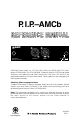
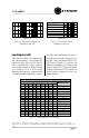
P. I.P.–AMCb AMC Programmable Input Processor (P.I.P.) OUTPUT INPUT 3 GND 1 2 ©2003 by Crown Audio, Inc., P.O. Box 1000, Elkhart, IN 46515-1000 U.S.A. Telephone: 574-294-8000. Fax: 574-294-8329. Trademark Notice: PIP, PIP2 and Studio Reference are trademarks and Crown, Macro-Tech, Com-Tech, IOC and P.I.P. are registered trademarks of Crown International. Other trademarks are the property of their respective owners.
P.I.P.
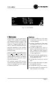
P.I.P.–AMCb AMC Programmable Input Processor (P.I.P.) OUTPUT INPUT 3 GND 1 2 Fig. 1.1 P.I.P.–AMCb 1 Welcome Features Congratulations on your purchase of Crown’s P.I.P. ®–AMCb. PIPTM modules are designed to quickly install in the back of many Crown amplifiers. PIP stands for “Programmable Input Processor.” Each PIP has features that expand the capabilities of your amplifier, enabling you to customize it for your particular needs.
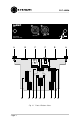
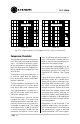
P.I.P.–AMCb AMC Programmable Input Processor (P.I.P.) A B OUTPUT INPUT C C DAISY OUT CROSSOVER 1 2 3 4 5 6 ON 1 2 3 4 5 6 F G CH1 THRESHOLD ON 1 2 3 4 5 6 ON E H G I Fig. 2.
P.I.P.–AMCb 2 Facilities DAISY OUT A. Thumb Screws (EQ and compression) to the daisy chain output. PROC LO LO EQ LO THRU EQ HI HI PROC HI Use these thumb screws to fasten the PIP to the amplifier. A circlip prevents them from falling out. B. Auxiliary SIP sockets G. CH1/CH2 OUT Jumpers The two auxiliary SIP sockets hold spare crossover SIP resistors. SIPs with values of 33, 20 and 10 kohm are provided. Crossover frequencies are chosen using various SIP combinations.
P.I.P.–AMCb 3 Installation CROSSOVER Before installing any P.I.P. in your amplifier, turn down the amplifier’s level controls, turn off the amplifier and disconnect the AC power. Even though the amplifier is off, there could still be enough energy in the circuitry to cause electric shock. Crossover Selection The crossover is a fourth-order Linkwitz-Riley type with state-variable topology.
P.I.P.–AMCb 0˚ CHANNEL 1 –45˚ CHANNEL 2 0 –90˚ CHANNEL 1 CHANNEL 2 –135˚ dB –6 –180˚ –225˚ –12 –270˚ –315˚ 200 1K 10 K 200 20 K 300 400 1K 500 FREQUENCY (Hz) FREQUENCY (Hz) Fig. 3.2 Crossover Frequency Response (800 Hz) Fig. 3.3 Crossover Phase Response (800 Hz) Low-Frequency EQ After the crossover, low frequencies are equalized by a second-order high pass filter with a Q of 2.
P.I.P.–AMCb +6 dB 0 FLAT –6 2 10 100 1K FREQUENCY (Hz) Fig. 3.5 Low-Frequency EQ Response Curves Overall equalizer boost is a combination of the shelving and roll-off filters (see Figures 3.7a and 3.7b). Notice that the shelving network can be disabled (set to FLAT) but the low pass filter is always active. Constant-Directivity Horn EQ After the crossover, the high-frequency band is equalized for the inherent roll-off in constant-directivity horns.
P.I.P.–AMCb +18 +18 HORN EQ = 1.8 kHz HORN EQ = 2.2 kHz +12 +12 +6 +6 dB dB 0 0 –6 –6 –12 –12 –18 –18 200 1K 10 K 20 K 200 FREQUENCY (Hz) 1K 10 K 20 K 10 K 20 K 10 K 20 K FREQUENCY (Hz) +18 +18 HORN EQ = 2.4 kHz HORN EQ = 3.2 kHz +12 +12 +6 +6 dB dB 0 0 –6 –6 –12 –12 –18 –18 200 1K 10 K 20 K 200 FREQUENCY (Hz) 1K FREQUENCY (Hz) +18 +18 HORN EQ = 6.
P.I.P.–AMCb +18 +18 HORN EQ = 10 kHz HORN EQ = FLAT +12 +12 +6 +6 dB dB 0 0 –6 –6 –12 –12 –18 –18 200 1K 10 K 20 K FREQUENCY (Hz) 200 1K 10 K 20 K FREQUENCY (Hz) Fig. 3.7b High-Frequency EQ Response Curves (800 Hz Crossover) Compressor Threshold Tracing the signal path, the compressors follow the crossover and equalizers. Variable-threshold signaldriven compressors are provided for both the high and low frequencies, but by default, the compressors are error-driven.
P.I.P.–AMCb THRESHOLD CONVERSION W @ 8Ω RMS Volts THRESHOLD CONVERSION W @ 8Ω RMS Volts THRESHOLD CONVERSION W @ 8Ω RMS Volts W @ 2Ω W @ 4Ω 34.0 10300 5130 2570 143 155 35.2 11000 5520 2760 149 333 167 36.5 11900 5930 2960 154 717 358 179 37.9 12700 6370 3190 160 9.31 770 385 192 39.2 13700 6850 3420 165 11.6 9.65 827 414 207 40.7 14700 7360 3680 172 25.0 12.5 10.0 889 445 222 42.2 15800 7910 3950 178 53.7 26.9 13.4 10.4 955 478 239 43.
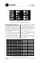
P.I.P.–AMCb CH1 & CH2 COMPRESSOR THRESHOLD SETTINGS Switch Settings Threshold* (RMS Volts) 1 2 3 4 5 6 MA-3600VZ OFF OFF OFF OFF OFF OFF 10.5 All Other Amps 8 ON OFF OFF OFF OFF OFF 14 10.5 OFF ON OFF OFF OFF OFF 17 13 ON ON OFF OFF OFF OFF 20 15.5 OFF OFF ON OFF OFF OFF 23.5 18 ON OFF ON OFF OFF OFF 27 20.5 OFF ON ON OFF OFF OFF 30 23 ON ON ON OFF OFF OFF 33.5 25.5 OFF OFF OFF ON OFF OFF 36.
P.I.P.–AMCb CH1 & CH2 COMPRESSOR THRESHOLD SETTINGS Switch Settings Threshold* (RMS Volts) 1 2 3 4 5 6 MA-3600VZ OFF OFF OFF OFF OFF ON 115.5 All Other Amps 88 ON OFF OFF OFF OFF ON 118.5 90.5 OFF ON OFF OFF OFF ON 122 93 ON ON OFF OFF OFF ON 125 95.5 OFF OFF ON OFF OFF ON 128.5 98 ON OFF ON OFF OFF ON 131.5 100.5 OFF ON ON OFF OFF ON 135 103 ON ON ON OFF OFF ON 138 105.5 OFF OFF OFF ON OFF ON 141.
P.I.P.–AMCb Output Channel Control The P.I.P.–AMCb provides several options for routing high and low frequency signals from each of its two output channels to the amplifier inputs. The “CH OUT” jumpers are used to set this (see Figure 2.1). These jumpers can be set so that each amplifier channel is supplied with either the high- or low-frequency signal.
P.I.P.–AMCb Input/Output Wiring A balanced mono input is provided via a female 3-pin XLR connector where pin 1 is ground, pin 2 is noninverting, and pin 3 is inverting. Figures 3.11 and 3.12 illustrate this: GND 1 3 2 – + FROM SOURCE INPUT Fig. 3.11 Balanced Input Wiring 1 SHIELD 3 2 INPUT + FROM SOURCE Fig. 3.12 Unbalanced Input Wiring The “daisy chain” output is a balanced output.
P.I.P.–AMCb Installation You may need a phillips screwdriver to remove the existing PIP module or panel from your amplifier. CAUTION: Before connecting this or any PIP module, it is important to turn your amplifier's level controls down, turn it off and remove the AC power. Don’t touch the circuitry. Even though the amplifier is off, there could still be enough energy remaining to cause electric shock. 1.
P.I.P.–AMCb 4. Tighten the two PIP mounting thumbscrews. 5. Connect input and output wiring as described in the preceding section (Input/Output Wiring). 6. Plug in the amplifier and turn it on. Adjust its level controls to a desired setting. (In Dual mode, the level controls can now be used to balance the low and high frequencies.) Do not tamper with the circuitry. Circuit changes made by unauthorized personnel, or unauthorized circuit modifications are not allowed.
P.I.P.–AMCb 4 Specifications Signal to Noise Ratio: Greater than 85 dB (equivalent input noise) from 20 Hz to 20 kHz. Common Mode Rejection: Greater than 90 dB at 60 Hz; greater than 60 dB at 20 kHz. Crosstalk: Greater than 46 dB below the signal level at 20 kHz. Harmonic Distortion: Less than 0.05% THD at 1 kHz with any setting and no compression. Less than 0.5% (either channel) at 800 Hz crossover with 6 dB of compression. Input Impedance: Nominally 50 kohms balanced and 25 kohms unbalanced.
P.I.P.
For Technical Support contact: Crown Audio Technical Support Group 1718 W. Mishawaka Rd., Elkhart, Indiana 46517 U.S.A. Phone: 800-342-6939 (North America, Puerto Rico and Virgin Islands) or 574-294-8200 Fax: 574-294-8301 Internet: http://www.crownaudio.