P.I.P.–BEQ BEQ – + – OUT + IN CH-2 – + – IN + OUT CH-1 Programmable Input Processor (P.I.P.) © 1997 by Crown International, Inc., P.O. Box 1000, Elkhart, IN 46515-1000 U.S.A. Telephone: 219-294-8000. Fax: 219-294-8329. P.I.P. modules are produced by the Professional Audio Division of Crown International, Inc. Trademark Notice: Crown ® and P.I.P.® are registered trademarks of Crown International, Inc. Other trademarks are the property of their respective owners. Printed on recycled paper.
P.I.P.
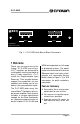
P.I.P.–BEQ BEQ – + – OUT + IN CH-2 – + – IN + OUT CH-1 Programmable Input Processor (P.I.P.) Fig. 1.1 P.I.P.–BEQ with Barrier Block Connectors 1 Welcome Thank you for purchasing the Crown P.I.P.–BEQ accessory. P.I.P.® modules are designed to install quickly into the rear panel of many Crown amplifiers. P.I.P. stands for ‘Programmable Input Processor.’ Their versatile features expand the capabilities of your amplifier and enable you to customize it for your particular needs.
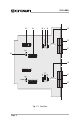
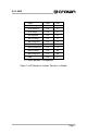
Page 4 EQ EQ SUB S101 Fig. 2.1 Facilities E BY ON 1 2 3 4 5 6 7 8 9 10 BY F S100 FUL NORM R140 802 ON 1 2 3 4 5 6 7 8 9 10 ON 1 2 3 4 5 6 7 8 9 10 NORM S201 G B F EQ EQ S200 SUB 802 H I BY ON 1 2 3 4 5 6 7 8 9 10 A FUL R240 BY A E D C P.I.P.
P.I.P.–BEQ 2 Facilities A. DIP Switches These DIP switches select the EQ setting for the various Bose loudspeaker models with which the P.I.P.-BEQ can be used. Mating solderless plugs are included for barrier block connectors. The plugs are labelled for correct wiring. B. Model 802 Jumper F. Input Connector This jumper is used with the DIP switches to select the model 802 response. Balanced 3-pin barrier block or XLR connectors are used for input to each channel.
P.I.P.
P.I.P.
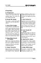
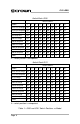
P.I.P.–BEQ 3 Installation The internal jumpers and switches of the P.I.P.-BEQ must be set prior to installation. See the previous section for a description of each jumper. The graphs in Figures 3.1 through 3.11 show the typical frequency response for all valid switch combinations. 20 15 10 5 dB 0 -5 -10 -15 -20 10 100 1000 10000 100000 Frequency (Hz) Fig. 3.1 Equalization Response for Model 25, 32, Full Range 20 15 10 5 dB 0 -5 -10 -15 -20 10 100 1000 10000 100000 Frequency (Hz) Fig. 3.
P.I.P.–BEQ 20 15 10 5 dB 0 -5 -10 -15 -20 10 100 1000 10000 100000 Frequency (Hz) Fig. 3.3 Equalization Response for Model 502A, Full Range 20 15 10 5 dB 0 -5 -10 -15 -20 10 100 1000 10000 100000 Frequency (Hz) Fig. 3.4 Equalization Response for Model 502A, Bi-Amplified 20 15 10 5 dB 0 -5 -10 -15 -20 10 100 1000 10000 100000 Frequency (Hz) Fig. 3.
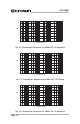
P.I.P.–BEQ 20 15 10 5 dB 0 -5 -10 -15 -20 10 100 1000 10000 100000 Frequency (Hz) Fig. 3.6 Equalization Response for Model 802, Bi-Amplified 20 15 10 5 dB 0 -5 -10 -15 -20 10 100 1000 10000 100000 Frequency (Hz) Fig. 3.7 Equalization Response for Model 402, Full Range 20 15 10 5 dB 0 -5 -10 -15 -20 10 100 1000 10000 100000 Frequency (Hz) Fig. 3.
P.I.P.–BEQ 20 15 10 5 dB 0 -5 -10 -15 -20 10 100 1000 10000 100000 Frequency (Hz) Fig. 3.9 Equalization Response for Model 8, Full Range 20 15 10 5 dB 0 -5 -10 -15 -20 10 100 1000 10000 100000 Frequency (Hz) Fig. 3.10 Equalization Response for Model 8, Bi-Amplified 20 15 10 5 dB 0 -5 -10 -15 -20 10 100 1000 10000 100000 Frequency (Hz) Fig. 3.
P.I.P.–BEQ 3.1 Biamping Those who are not familiar with Bose products may need to understand that Bose handles the biamping of its loudspeaker products in a different manner than the traditional industry practice. Standard industry practice is to split the audio bandwidth into two discrete sections divided by 2ndorder (12-dB/octave) or steeper filters (see Figure 3.12).
P.I.P.–BEQ 3.2 Installation Procedures You may need a phillips screwdriver to remove the existing P.I.P. module or panel from your amplifier. the unit in until it is seated against the mounting bracket (see Figure 3.17). CAUTION: Before connecting this or any P.I.P. to your amplifier, it is important to turn its level controls down, turn it off and remove the AC power. Don’t touch the circuitry. Even though the amplifier is off, there could still be enough energy remaining to cause electric shock.
P.I.P.–BEQ sert the assembly into the P.I.P. opening in the back of the amplifier. 4. Tighten the two P.I.P. mounting thumbscrews. 5. Connect input and output wiring. 6. Plug in the amplifier and turn it on. Adjust its level controls to a desired setting. (In Dual mode, the level controls can now be used to balance the low and high frequencies.) Do not tamper with the circuitry. Circuit changes made by unauthorized personnel, or unauthorized circuit modifications are not allowed.
P.I.P.–BEQ 4 Specifications Note: All specifications are referenced to a 0.775-V input signal. Signal to Noise: Greater than 90 dB from 20 Hz to 20 kHz in Bypass mode. Greater than 85 dB in EQ mode. Frequency Response: ±0.1 dB from 20 Hz to 20 kHz in Bypass mode. ±2 dB from the response curves in Figure 3.1 through 3.6 in EQ mode. Harmonic Distortion (THD): Less than 0.05% THD from 20 Hz to 20 kHz in Bypass mode with a 0 dBu input signal. Less than 0.1% THD from 20 Hz to 20 kHz in EQ mode at 0 dBu.
P.I.P.–BEQ For Technical Support contact: Crown Audio Division Technical Support Group Plant 2 SW, 1718 W. Mishawaka Rd., Elkhart, Indiana 46517 U.S.A. Phone: 800-342-6939 (North America, Puerto Rico and Virgin Islands) or 219-294-8200 Fax: 219-294-8301 Fax Back (North America only): 800-294-4094 or 219-293-9200 Fax Back (International): 219-294-8100 Internet: http://www.crownintl.