® FM1000A RF Amplifier Package User's Manual ©2005 Crown Broadcast, a division of International Radio and Electronics, Inc. 25166 Leer Drive, Elkhart, Indiana, 46514-5425 U.S.A.
Revision Control Revision Print Date Initial Release (Rev. 0) 900413-1 November 1998 Revision 1 April 2002 Revision 2 May 2005 Important Notices ©2005, Crown Broadcast, a division of International Radio and Electronics, Inc. All rights reserved. No part of this publication may be reproduced, transmitted, transcribed, stored in a retrieval system, or translated into any language in any form by any means without the written permission of Crown International, Inc. Printed in U.S.A.
Contents Section 1—Getting Acquainted 1.1 Your Amplifier Package ....................................................................................... 1–2 1.2 Amplifier Package Specifications ......................................................................... 1–3 1.3 Safety Considerations .......................................................................................... 1–4 1.3.1 Dangers .........................................................................................................
.2 PS1000 Power Supply ...................................................................................... 4–4 4.2.1 AC Input Board ............................................................................................. 4–5 4.2.2 PFC (Power Factor Correcting) Switching Board .......................................... 4–5 4.2.3 DC Output Board .......................................................................................... 4–6 4.2.4 Cooling Fans ...........................................
I INFORMATION Section 1—Getting Acquainted This section provides a general description of the FM1000A power amplifier system and introduces you to safety conventions used within this document. Review this material before installing or operating the amplifier and power supply.
I 1.1 Your Amplifier Package The FM1000A is a highly efficient amplifier package designed to set a new standard in FM transmitter design offering modularity, ease of use, and long-term reliability. The FM1000A package includes a PA1000 amplifier, PS1000 power supply, and an FM1K accessory pack. The PA1000 broadband amplifier requires no tuning and typically provides 80% RF efficiency across the band. The PS1000 power supply is power factor corrected and 90% efficient.
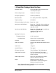
1.2 Amplifier Package Specifications RF Power Output: 100 to 1100 watts continuous with remote controlled power adjust RF Drive Requirement: 30 watts for full output RF Output Impedance: 50 ohms (unbalanced) Maximum SWR: 1.
I 1.3 Safety Considerations Crown Broadcast assumes the responsibility for providing you a safe product and safety guidelines during its use. “Safety” means protection to all individuals who install, operate, and service the transmitter as well as protection of the transmitter itself. To promote safety, we use standard hazard alert labeling on the product and in this manual. Follow the associated guidelines to avoid potential hazard. 1.3.1 Dangers DANGER represents the most severe hazard alert.
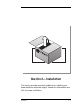
® Section 2—Installation This section provides important guidelines for installing your power amplifier and power supply. Review this information carefully for proper installation.
2.1 Operating Environment You can install the FM1000A amplifier system in a standard 19–inch component rack or on a suitable surface such as a bench or desk. In any case, the area should be as clean and well-ventillated as possible. The power supply must be installed directly above or below the power amplifier (for the included dressed cables to reach their respective connectors). 2.
2.4 Preinstallation 2.4.1 Power Amplifier Modules The PA1000 incorporates four power amplifiers (two each in two modules). Due to possible damage during shipment, the power modules have been removed. Follow these steps to install the modules: 1. Remove the front panel of the PA1000 (four screws). 2. Taking ESD precautions (see page 2–2), unpack the power modules and place them on your work area with the circuit sides up. Connector Warning Label Slide Rail Illustration 2–1 Power Amplifier Module 3.
2.4.2 Hubble Twist Lock® Connector Wiring Prepare the wiring for the Hubble Twist-Lock® connector in the following manner before connecting to your AC power source: 1. Use round cord with a diameter of 0.385–0.780 inches (10–20 mm), Type SJ 12/3 – 10/3; Type S 16/3 – 10/3. 2. Select conductor size from your National Electrical Code®. 3. Slide the cover onto the cord. Remove insulation from cable and conductors as shown in Illustration 2–3. Do not tin conductors.
2.5 Installation 1. Mount the units in an appropriate 19–inch wide cabinet. The power supply must be installed directly below the power amplifier for the included cables to reach their respective connectors (see illustration 2–4 below). Note: The PS1000 weighs approximately 40 pounds (18.1 kg); the PA1000, approximately 43 pounds (19.5 kg). Use help to install. 2.
8. Using the supplied connector, tie together pins 6 and 7 of the Remote I/O connector. The amplifier will not operate without this connection or a remote switch on these pins. (See Section 2.6 for Remote I/O connection.) 9. If monitoring of the output signal is desired, connect the RF monitor cable to the BNC connector on the PA1000. 10. Connect the DC input/output cables between the PA1000 and the PS1000 as illustrated (Illustration 2–4). The connector end with the ground lead connects to the PA1000.
the level up to that limit and down to zero. When a specific output power level is set, the Metering and Control Board controls and maintains the setting to keep the power constant. The location of the Local Power Adjust (R62), the on-board Raise and Lower switches (SW3 & SW4), and the Local/Remote slide switch (SW5) are shown below.
Pin # Function 1 PA#8 Current Monitor (a buffered metering output with 1 V = 2 A) 2 PA#7 Current Monitor (a buffered metering output with 1 V = 2 A) 3 Ground 4 Remote RAISE Power (a momentary switch, on this pin, when held low will raise the power level 10 watts every 0.5 seconds) 5 Remote RF Power Control (a resistor to ground on this pin reduces RF power output level below internal limits. See Section 2.
Section 3—Operation This section provides general operating parameters of your power amplifier system and a detailed description of the front panel display.
3.1 Initial Power-up Procedures These steps summarize the operating procedures you should use for the initial operation of the power amplifier and power supply. More detailed information follows. 1. Ensure that the external remote control unit is properly connected (See the Pin Out Description Table, Section 2.6, page 2–8 for proper pin configuration). If not using a remote control unit, pin 7 must be tied to ground pin 6. 2. Connect Antenna. 3.
6. Before power-up, place the Local/Remote switch (located on the Metering & Control board behind the front panel) in the Local position and adjust the output power limit to the mid-level position using the Local Power Adjust, also on the Metering & Control board (see Illustration 3–2 below). The unit is normally shipped with this setting. See Section 2.6 for setting up remote operation and using the on-board remote buttons and other controls. 7.
10. Verify that the following conditions are present as indicated by the PA1000’s Digital Multimeter: a. In Ref—Should read between 0.4 and 0.8 volts (0.5 nominal, dependent upon power input level). b. SWR—Should read 1.05 to 1.5. c. ALC—Should read between 4.00 and 6.00 volts for 1.1 kW output (less for lower output or danger conditions, i.e. high SWR). d. Power Out—Should read 1.10 for 1.1 kW output. e. PA Temp—Should read 35 to 50°C with ambient temperature of 25°C.
3.2.2 DC Power Switch The main on/off power switch located on the front panel of the power supply controls high voltage output. (The control circuit activates this voltage.) Power I O ® Power Switch Illustration 3–5 DC Power Switch 3.2.3 Interlock Switch This switch is located on the fan mounting bracket in the power supply. When the top cover of the power supply is removed, the Interlock Switch interrupts the power supply control circuit disabling the high and low voltage supplies.
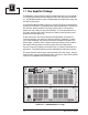
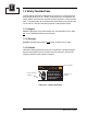
3.3 Digital Multimeter The 3–digit numeric display in the upper left corner of the front panel provides information on the amplifier’s operation. Use the “up” and “down” push-buttons to select one of the following parameters as indicated by a green LED.
3.4 Fault Indicators Faults are indicated by illuminated red LED’s when the following occurs: Antenna—Load SWR exceeds 1.5:1. ALC voltage is reduced to limit the reflected RF power. RF Drive—Lack of or insufficient RF drive. If the RF drive fault LED is lit, input drive must be increased. To achieve full output power, 30 watts of input drive is required. CAUTION Possible equipment damage! Do not exceed 40 watts of input drive. Damage to the PA1000 will result if this level is exceeded.
3.5 Fuse Indicators The PA1000 consists of two field-replacable power modules with two amplifiers in each module. Each of the paralleled amplifiers is protected by a 10 ampere fast-acting fuse. When a fuse opens, the indicator light next to it illuminates. Fuses 3 and 4 represent amplifiers 1 and 2 on the top right module. Fuses 7 and 8 represent amplifiers 3 and 4 on the lower right power module.
, erono due persone che ab ondo bian to m o ue s non ha la dispozion in q e do dice che o si farl o. , un e M e non c'e nulla nel mond fors o re che ch o a le d iam i dic se n la matita ci insegna a non do co parl n e v are scri pers ue d a no on e che a , ero m bbia ondo no to m ue s non ha la dispozion in q e do dice che farl no si o.
uesto mondo, in rqse, uno si dice fo diciamo che se scrivendo con maquesto mondo, in rse, uno si dice fo diciamo che se scrivendo con ma scrivendo con ma uesto mondo, in rqse, uno si dice fo diciamo che se scrivendo con ma scrivendo con ma uesto mondo, in rqse, uno si dice fo diciamo che se scrivendo con madiciamo che se scrivendo con ma Introduction The FM1000A is a solid state RF amplifier package designed to deliver 500 to 1000 watts.
4.1.3 Backplane Assembly The backplane assembly is located in the vertical center of the PA1000 behind the power modules. The Backplane Assembly is the common connection point for the major sections of the transmitter. This assembly consists of the Input Divider Board, Output Combiner Board, and Backplane Interconnect Board. 4.1.3.1 Backplane DC Interconnect Board This board is located nearest the metal inner brace of the chassis.
uesto mondo, in rqse, uno si dice fo diciamo che se scrivendo con maquesto mondo, in rse, uno si dice fo diciamo che se scrivendo con ma scrivendo con ma uesto mondo, in rqse, uno si dice fo diciamo che se scrivendo con ma scrivendo con ma uesto mondo, in rqse, uno si dice fo diciamo che se scrivendo con madiciamo che se scrivendo con ma 4.1.5 Metering and Control Board The Metering and Control Board is located above the upper left cavity.
4.2.1 AC Input Board The AC Input Board is located on the left side of the PS1000. AC power from the circuit breaker connects to the AC Input Board where it connects to a ±12 volt DC power supply and three relays. The ±12 volts is used to close the three relays when the DC Power Switch on the front panel is switched on. In addition, the ±12 volts are supplied to the PA1000 for use in the Control and Metering Board.
uesto mondo, in rqse, uno si dice fo diciamo che se scrivendo con maquesto mondo, in rse, uno si dice fo diciamo che se scrivendo con ma scrivendo con ma uesto mondo, in rqse, uno si dice fo diciamo che se scrivendo con ma scrivendo con ma uesto mondo, in rqse, uno si dice fo diciamo che se scrivendo con madiciamo che se scrivendo con ma 4.2.3 DC Output Board The DC Output Board is located in the back of the unit directly behind the PFC Switching Board.
TROUBLE Section 5—Troubleshooting This section describes procedures for service personnel to diagnose and troubleshoot potential fault conditions in the power amplifier and power supply.
TROUBLE 5.1 Troubleshooting Flow Chart Analysis Does your amplifier have output power? Is power output at the proper level? Yes Yes No Do you have power now? No Is exciter delivering sufficient RF drive? (Check In Ref meter reading.) Are there any fault indicators? Yes See Section 3.1 Initial Power-up procedures. No Yes No Is your exciter turned on? See Section 3.1 Initial Power-up procedures. Yes Yes No No Turn the exciter on. Antenna: See Section 5.3.
5.2 Digital Multimeter Parameters The following procedures are general in nature; for in-depth service, and repair see the Service & Support section of this manual. WARNING Lethal voltages present! Only technically qualified individuals shoud attempt troubleshooting or service procedures. If any abnormal readings are displayed for any of the following parameters on the Digital Multimeter, try troubleshooting in the following manner: 5.2.
TROUBLE 5.2.5 PA Temp The meter should read between 35–50°C with an ambient temperature of 25°C. If temperature is 75°C or above, then check and do the following: ❑ Ambient temperature higher than 50°C; reduce temperature. ❑ Restricted air flow; remove any obstructions, clean dirty air filters by using mild detergent and warm water. ❑ Possible antenna mismatch; check for icing, moisture in the feedline, and secure antenna connections.
5.3 Fault Indicators If one of the LED fault indicators is illuminated red, troubleshoot using the following suggestions: 5.3.1 Antenna Antenna mismatch. ❑ Effects from inclement weather conditions such as icing. ❑ Check for moisture in the feedline. ❑ Secure antenna connections. 5.3.2 RF Drive Denotes lack of or insufficient drive level. ❑ Ensure proper drive level of 25–30 watts input power. ❑ Check RF input cable for secure connection. 5.3.
TROUBLE a. The circuit breaker is located on the rear panel of the power supply. If the breaker has popped out, reset it by pushing it in. If the breaker continues to trip, check for a short circuit. b. Check each fan with a volt-ohm meter by disconnecting and testing it for a short circuit. Replace the fan/fans as needed (see Section 7). c. If none of the fans have short circuits, there is damage on the winding of the transformer. It will have to be replaced (see Section 7). 5.3.
Section 6—Reference Drawings The illustrations in this section may be useful for making adjustments, taking measurements, troubleshooting, or understanding the circuitry of your RF power amplifier and power supply.
6.
6.
6–4 AC INPUT 240 VAC AC CIRCUIT BREAKER NEUTRAL 360 VDC AC INPUT CCA RECTIFIER 220 VDC GROUND PFC & CONTROL CCA + 0 to 50 VDC 360 VDC CONTROL +/ 12 VDC POWER SWITCH 9-PIN DSUB VOLTAGE BOOST INDUCTOR PS CONTROL FM1000A User’s Manual Illustration 6–4 PS1000 Block Diagram DC OUTPUT CCA RETURN
6–8 FM1000A User’s Manual Illustration 6–5 PA1000 Block Diagram
Note: All bypass capacitors are 0.
Ribbon Cables and Connectors Ribbon Cables and Connectors 6–14 FM1000A User's Manual
Notes: 6–16 FM1000A User's Manual
Section 7—Service and Support We understand that you may need various levels of support or that the product could require servicing at some point in time. This section provides information for both of these scenarios.
7.1 Service The product warranty (see opposite page) outlines our responsibility for defective products. Before returning a product for repair or replacement (our choice), call our Customer Service department using the following telephone number: (866) 262-8917 Our Customer Service Representative will give you further instructions regarding the return of your product. Use the original shipping carton or a new one obtained from Crown.
Crown Broadcast Three Year Limited Product Warranty SUMMARY OF WARRANTY Crown Broadcast, IREC warrants its broadcast products to the ORIGINAL PURCHASER of a NEW Crown Broadcast product, for a period of three (3) years after shipment from Crown Broadcast. All products are warranted to be free of defects in materials and workmanship and meet or exeed all specifications published by Crown Broadcast. Product nameplate with serial number must be intact and not altered in any way.
Notes: 7–4 FM1000A User's Manual
Factory Service Instructions To obtain factory service, complete the bottom half of this page, include it with the unit, and ship to: International Radio and Electronics Company, Inc. 25166 Leer Drive Elkhart, Indiana, U.S.A. 46514-5425 For units in warranty (within 3 years of purchase from any authorized Crown Dealer): We pay for ground UPS shipments from anywhere in the continental U.S. and Federal Express Second Day service from Hawaii and Alaska to the factory and back to you.
A B C Glossary The following pages define terms and abbreviations used throughout this and other Crown Broadcast manuals.
A B C AF Audio Frequency; the frequencies between 20 Hz and 20 kHz in the electromagnetic spectrum. ALC Automatic Level Control AM Amplitude Modulation; the process of impressing information on a radio-frequency signal by varying its amplitude. bandwidth The range of frequencies available for signalling. BCD Binary-Coded Decimal; a digital system that uses binary codes to represent decimal digits.
exciter FET (1) A circuit that supplies the initial oscillator used in the driver stage. (2) A transmitter configuration which excludes stereo generation and audio processing. Field-Effect Transistor frequency synthesizer A circuit that generates precise frequency signals by means of a single crystal oscillator in conjunction with frequency dividers and multipliers. FM Frequency Modulation; the process of impressing information on a radio signal by varying its frequency.
A B C PAI Power Amplifier Current PAV Power Amplifier Voltage pilot A 19–kHz signal used for stereo transmissions. pre-emphasis The deliberate accentuation of the higher audio frequencies; made possible by a high-pass filter. processing The procedure and/or circuits used to modify incoming audio (keeping its level around 75 kHz deviation) to make it suitable for transmission. receiver An option which adds incoming RF capability to an existing transmitter. See also "Translator.
SWR Standing-Wave Ratio; on a transmission line, the ratio of the maximum voltage to the minimum voltage or maximum current to the minimum current; also the ratio of load impedance to intended (50 ohms) load impedance. THD Total Harmonic Distortion translator A transmitter designed to internally change an FM signal from one frequency to another for retransmission. Used in conjunction with terrestrial-fed networks.
Index A H AC Input Board 4–5 AC Power 1–3 AC power 2–4 ALC 3–4, 5–3 Antenna 3–7 mismatch 5–5 antenna 2–5 Humidity Range 1–3 I In Ref 3–4, 5–3 Input Divider Board 4–3 Installation 2–5 Interlock Switch 3–5 B L Backplane Assembly 4–3 Backplane DC Interconnect Board 4–3 Board Layouts 6–3 labels 1–4 C Circuit Breaker 3–4 Combiner Board 4–2 Connections 2–5 Connectors Hubble Twist Lock® 2–4 Hubble Twist-Lock 2–6 connectors 2–5 D DC Fuse and Power Distribution Board 4–4 DC Output Board 4–6 DC Power Switch
R T remote I/O 2–7 RF Drive Requirement 1–3 RF Harmonics 1–3 RF Output Impedance 1–3 RF output power 1–2 RF Power Output 1–3 RF power output 1–2 RU spaces 1–2 Tot Current 5–4 transmitter package 1–2 Troubleshooting Flow Chart 5–2 U S Weight 1–3 S/N Ratio 1–3 Safety 1–4 Schematics 6–3 Spurious Products 1–3 SWR 1–3, 3–4, 5–3 Index-ii Unpacking 2–2 W