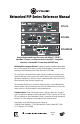
Networked PIP Series Reference Manual TCP / IQ PIP-LITE ANALOG AUDIO INPUTS PIP-USP3 IN USE/ CONDUCTOR LINK/ ACTIVITY tm PIP-USP3/CN Network Programmable Input Processors with HiQnet™, TCP/IQ™ , SmartAmp ™ Features, Load Supervision for Crown PIP2™ -Compatible Amplifiers, and CobraNet™ Connectivity (USP3/CN only) Obtaining Other Language Versions: To obtain information in another language about the use of this product, please contact your local Crown Distributor.
Networked PIP Series Crown Technical Support 1718 W. Mishawaka Rd., Elkhart, Indiana 46517-9439 U.S.A. Phone: 800-342-6939 (North America, Puerto Rico and Virgin Islands) or 574-294-8200 Fax: 574-294-8301 Internet: http://www.crownaudio.com WATCH FOR THESE SYMBOLS. The exclamation point triangle is used to alert the user to important operating or maintenance instructions. The lightning bolt triangle is used to alert the user to the risk of electric shock.
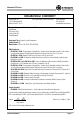
Networked PIP Series DECLARATION of CONFORMITY Crown Audio, Inc. 1718 W. Mishawaka Rd. Elkhart, IN 46517 U.S.A. FOR COMPLIANCE QUESTIONS ONLY: Susan Whitfield 574-294-8289 swhitfield@crownintl.
Networked PIP Series Quick Install Procedure This procedure is provided for those who would like to install the PIP card in the shortest time possible and are already familiar with Crown’s IQ System® or Harman Pro System Architect and HiQnet or TCP/IQ. Less experienced installers or those wishing a full explanation of the installation procedure are encouraged to go to Section 3 where the full installation procedure is described. Prepare the amplifier: 1.
Networked PIP Series Table of Contents FCC Compliance Notice .............................................................. 2 Declaration of Conformity ............................................................ 3 Quick Install Procedure ................................................................ 4 Illustrations .................................................................................. 7 1 Welcome ..................................................... 9 1.1 Unpacking ..........................
Networked PIP Series Table of Contents (continued) 5.2.5 Thermal Headroom Level Monitor ............................ 29 5.2.6 Power/Standby Control ............................................. 29 5.2.7 Signal Mute .............................................................. 29 5.2.8 Polarity Inverter ....................................................... 30 5.2.9 Input Signal Fader .................................................... 30 5.2.10 Dynamic Gain Monitors (Ghost Faders) ..................
Networked PIP Series Table of Contents (continued) 6 Audio Signal Wiring and Network Basics ................ 45 6.1 A Closer Look at Audio Signal Wiring .................................45 6.2 Network Basics ....................................................................46 6.3 A Closer Look at CobraNet (PIP-USP3./CN only)................49 6.3.1 Fast Ethernet ...............................................................49 6.3.2 Audio Specs ............................................................
Networked PIP Series Illustrations (continued) 5.1 PIP-Lite Signal Flow Block Diagram .......................................24 5.2 PIP-USP3 and PIP-USP3/CN Signal Flow Block Diagram .................................................................................25 5.3 SLM Tab of the Control Panel .................................................37 5.4 Typical Impedance Test Plot of Full-Range Speaker ................40 5.5 Frequency Response of Amplifier and DSP in dBu..................41 5.
Networked PIP Series 1 Welcome PIP-Lite Analog TCP / IQ Figure 1.1 PIP Series Modules ANALOG AUDIO INPUTS PIP-USP3 DSP-based IN USE/ CONDUCTOR LINK/ ACTIVITY tm PIP-USP3/CN DSP-based Works with CobraNet The Crown® Networked PIP™ series includes the PIP-Lite, PIP-USP3, and PIP-USP3/CN. Each PIP (Programmable Input Processor) is a module for a PIP2™ compatible amplifier.
Networked PIP Series 1.1 Unpacking The unit is shipped in a protective antistatic bag. CAUTION: STATIC ELECTRICITY MAY DAMAGE THE UNIT. Use caution when handling the unit. Carefully ground yourself BEFORE touching the unit. Avoided unnecessary touching the components or solder pads on the circuit board. It is best to handle the unit by its front panel only. Please unpack and inspect the unit for damage that may have occurred during transit. If damage is found, notify the transportation company immediately.
Networked PIP Series 2 Controls, Indicators and Connectors 2.1 PIP-Lite A. Balanced Audio Input Connectors 3-pin removable barrier-strip connectors, one per channel. B. Preset Indicator Signals the number of the current preset, if active, by flashing a series of flashes equal to the current preset number. See Section 4.1.2. C. Reset/Preset Switch Used to change presets, restore settings to factory default or restore all the presets to the factory defaults.
Networked PIP Series 2.2 PIP-USP3 Please refer to Figure 2.3. A Balanced Audio Input Connector 3-pin removable barrier strip connector for each audio channel. B. AUX Connector AUX input, AUX output, and Listen Bus. C. Preset Indicator Signals the number of the current preset, if active, by flashing a series of flashes equal to the current preset number. See Section 4.1.2. D. Reset/Preset Switch Used to change presets, restore settings to factory default or restore all the presets to the factory defaults.
Networked PIP Series 2.3 PIP-USP3/CN A. Preset Indicator Signals the number of the current preset, if active, by flashing a series of flashes equal to the current preset number. See Section 4.1.2. B. Reset/Preset Switch Used to change presets, restore settings to factory default or restore all the presets to the factory defaults. During operations of the switch, the Data indicator flashes as an aid to the user. See Section 4.1.11. C.
Networked PIP Series 3 Installation Before beginning, please carefully note: CAUTION: STATIC ELECTRICITY MAY DAMAGE THE UNIT. Use caution when handling the unit. Carefully ground yourself BEFORE touching the unit. Avoided unnecessary touching the components or solder pads on the circuit board. It is best to handle the unit by its front panel only. 3.1 Prepare the PIP The PIP comes ready to install in the amplifier.
Networked PIP Series 3.3 Install the PIP Into the Amplifier EXACT CONFIGURATION OF AMPLIFIER AND RIBBON CABLES MAY VARY Carefully ground yourself to the chassis of the amplifier before installing the PIP. It is a good idea to maintain ground contact between yourself and the amplifier while inserting the module into the amplifier. Connect the PIP module to the amplifier. 1.
Networked PIP Series 3.4 Install the Wiring IMPORTANT: Please read the wiring rules below before installing the wiring. If your computer does not communicate with the network devices after installation and addressing, re-read this section, as well as Section 4.2 on addressing rules. 3.4.1 Wiring Rules • Connect each device to the network through its own cable in a Star Network. Do not connect them in a serial fashion (as was done with the previous IQ current loop method).
Networked PIP Series 3.4.2 Wiring Instructions 1. PIP-Lite and PIP-USP3 ONLY: Using a standard CAT5 cable, connect the network connector to a 100 Mb port on an Ethenet switch that is used to form the control network. For more detail see Section 6.2, Network Basics. If the PIP module is not to be connected to a control network, it can be temporaily connected to a computer’s Ethernet port with a crossover cable (TX and RX pairs switched) to set up the PIP module for desired operation.
Networked PIP Series 2. Connect the Audio Input Wiring. The PIP module is equipped with removable barrier block connectors for each channel’s input. See Section 5.1 for more detail on audio wiring. The USP3/CN allows the use of standard balanced audio inputs to act either as CobraNet backup, an emergency override of CobraNet audio, or as an audio input to the CobraNet network. See Section 5.1.6 for additional details.
Networked PIP Series 4 How to Set Up TCP/IP 4.1 Introduction Before you set up a TCP/IP network with addressing, it’s important to understand all the terms involved. The following glossary explains network terminology. 4.1.1 Glossary Network: A group of interconnected components, such as a central computer, network switching equipment, and other computers or devices.
Networked PIP Series If your audio network stands alone (it is not part of a larger network ) then the HOST ID identifies each device in the network. If your audio network is part of a venue's larger network, your network is actually a sub-network or subnet. In this case, the HOST ID can be further divided into two or more parts. The first part is the SUBNET ID. The other part is the DEVICE ID.
Networked PIP Series 4.2 TCP/IP Addressing Rules In the next section, you will be assigning static TCP/IP addresses to the devices in your network. When you do so, be sure to follow the addressing rules below. Otherwise, the computer may not communicate with the devices. 1. Turn off DHCP (automatic addressing). 2. Assign each device a static (fixed) IP address. An IP address is made of four numbers separated by periods. Each number can be zero to 255. 3.
Networked PIP Series 4.3 Network Setup Wizard The network setup wizard can assist you in setting up your network for the first time. Using the wizard, you can address your components and be informed of addressing and other errors in the system. Please note that this wizard is designed to work with devices that are on the same physical network segment as the computer it is running on. It will not work through a router.
Networked PIP Series Address Devices on the Network The box labeled Check for Errors will report to you if any devices in the system have misconfigured IP addresses, or if there are duplicate IQ or HiQnet addresses in the system. If there are, what happens next is dependent on what Action to Take is selected: Readdress all devices - this selection will be the default if 10 or more addressing errors are found in the system.
Networked PIP Series 5 Operation The PIP-Lite, PIP-USP3 and PIP-USP3/CN are network components that allow control and monitoring of the power amplifier over a standard 100 Mb Ethernet network. Connection to the control computer is made through its standard network adapter. The PIPs can function independently from the network control. Once the processing is configured, the module's non-volatile memory allows the amplifier to continue to function with no external control.
Reference Manual s Input Source Selector s Auto Standby Gate Input Meter Auto Standby Gate Input Meter Input Compressor Input Compressor Input Delay Input Delay Band Pass Filters and Gain EQ Filters Band Pass Filters and Gain Signal Generators EQ Filters EQ Filters EQ Filters Output Delay Output Delay Output Fader and Mute Output Fader and Mute Output Limiters Output Limiters Networked PIP Series Figure 5.2 shows the system block diagram of the USP3 and USP3/CN. Figure 5.
Networked PIP Series 5.1 Hardware 5.1.1 Data Indicator An amber Data indicator is provided on the front panel. It flashes whenever a command addressed to the PIP is received. To assist with troubleshooting, an option that forces the data indicator to remain lit is available through the software. Some Crown amplifiers also have a data indicator on their front panels. In these cases this indicator will light simultaneously as the PIP’s Data indicator. 5.1.
Networked PIP Series 5.1.7 CobraNet In-Use/Conductor Indicator (USP3/CN only) The indicator on the left side of each CobraNet RJ-45 connector turns ON if the port is inuse (i.e. the link is being used to transmit or receive active CobraNet traffic), and will blink if the device is also the conductor (the timing reference). 5.1.8 Balanced Audio Inputs This removable barrier block connector allows line level audio signals to be input to the PIP.
Networked PIP Series • The Cycle Preset Mode will advance the PIP through a defined range of presets on a low-to-high transition of the AUX input. The inversion object changes the activity to a highto-low transition. The range of presets is defined by the max preset and min preset controls. Once the max preset is reached the next defined AUX input event will cycle the PIP to the minimum preset. • AUX Input Inversion: This control allows the low state to activate the selected function.
Networked PIP Series 5.2 Features of All Three Modules The exact location of the following controls varies with the software. These features might be inaccessible from the standard control panel, but accessible from a custom control page. 5.2.1 User Presets The control settings for all the functions can be stored as presets. A total of ten presets can be saved in the PIP’s nonvolatile memory.
Networked PIP Series 5.2.8 Polarity Inverter The input signal polarity of each channel can be independently inverted. 5.2.9 Input Signal Fader Each input signal can be adjusted under software control. The gain range is +20dB to –80dB in 0.5dB steps. In addition to adjustment of the post input router signal, each Analog Audio Input has a separate Fader that allows the trim of the Analog Audio Input before the Input Router. 5.2.
Networked PIP Series The software offer many options to further report errors, including audible alerts, printout, email, pager, serial port and fax. The exact options vary depending if you are using System Architect or IQwic. The options are set in the software. The following describes each error source. CLIP: The PIP can be configured to report if an excessive number of clip events occur in either amplifier channel.
Networked PIP Series 5.2.18 Input Signal Compressor/Limiter An input signal compressor/limiter is available for each channel. Five parameters control this feature: Enable: Enables or disables this function. Threshold: Sets the level, in dBu, above which the compressor begins to attenuate the input signal. This level corresponds to the input level meter reading. The compressor is “feed-forward,” meaning that the level detection point is located before the gain control stage.
Networked PIP Series Release Time: Sets the release time of the compressor. The release time is defined as the time it takes the limiter to increase the output signal by 20 dB. The range is from 10 milliseconds to 10 seconds. 5.2.20 Average Power Limiter This limits the long-term output power of the amplifier. Four parameters control this limiter for each channel: Enable: Enables or disables this limiter.
Networked PIP Series 5.2.24 Load Supervision The load supervision feature allows real-time monitoring of the load connected to each amplifier channel. When enabled, the PIP continuously monitors the amplifier output voltage and current, and calculates the long-term average load impedance. The measured load impedance is compared against the user-defined high and low limits. If either limit is exceeded, the status indicator and, if enabled, the IQwic Error Reporting functions alert the user of the problem.
Networked PIP Series Most amplifier/load systems can be configured and supervised by following these steps: 1. Configure your audio system using a known “good” load, then enable the Load Supervision feature. 2. Provide typical program material at a level high enough to light the “test” indicator. 3. Run the system at this level until the average impedance stabilizes. This may take seconds to minutes depending on level, duty-cycle, etc. 4. Set the nominal impedance at the measured value average.
Networked PIP Series These anomalies are easily averaged out by the PIP supervision algorithm in most systems. However, there may be some extreme situations for very narrow bandwidth (i.e. single-note) signals and/or very widely varying loads that the algorithm simply cannot overcome. In these cases, widening the high and low limits will help decrease the “sensitivity” of supervision and decrease the chance of “nuisance” error reports. 5.3 PIP-USP3 and PIP-USP3/CN Features 5.3.
Networked PIP Series In addition to these unavoidable delays, additional delay can be added to each channel. Each channel is capable of 2.0 seconds of delay in 20.8 µs increments. Overall delay = inherent delay + coarse delay + fine delay. 5.3.4 Noise Generator Each channel has an independent uncorrelated noise generator that allows noise to be mixed into the audio signal. This is useful for noise masking applications and testing.
Networked PIP Series The SLM tab allows you to test network-PIP components for impedance vs. frequency and frequency response. The USP3 and USP3/CN include a signal generator to provide a swept sine-wave signal for the tests. Described below are the three sections of the SLM tab: Sweep, Channel SLM and Tolerance.
Networked PIP Series • Reference measures both the impedance-vs.-frequency and frequency response of a known good component. All other tests are compared to these results until a new reference is created. Impedance and Frequency Pass/Fail Indicators These show whether the channel passed or failed the selected test. Start/Stop Frequencies These are the lowest and highest frequencies of the displayed curve.
Networked PIP Series Curves Clicking on the "Curves" button will allow you to look at any of the curves that were generated as the result of tests performed. These curves are displayed in a separate Curve Viewer. Some typical curves are shown in Figures 5.4, 5.5 and 5.6. In Figure 5.4, find the File Menu at the top left of the impedance plot. The first choice is “Export View to .DIF...” .DIF is a common spreadsheet file format. “Notes” allows you to attach added information that will be saved in the file.
Networked PIP Series Figure 5.5 Frequency Response of Amplifier and DSP in dBu Figure 5.
Networked PIP Series 5.4 PIP-USP3/CN Features 5.4.1 Input Signal Router Each channel of the PIP’s signal processing has an Input Signal Router that allows the choice of audio signal that will be used by the channel. The user may choose one of the following configurations: • CobraNet Audio: This is the assigned CobraNet audio as setup in the CobraNet Input section of the software. See Section 6.3 for more details. Choices for the CobraNet Input are Channel 1, Channel 2, or a sum of Channels 1 and 2.
Networked PIP Series System Name This parameter is user-settable to any alpha-numeric string of 30 characters or less. The intended use is to communicate a unique name for the particular device to a network. The System Name object is stored in presets. System Description This parameter is configured at the factory and is read-only. The intended use is to communicate a unique device description to a network.
Networked PIP Series CobraNet Receive Channels Each CobraNet Bundle contains up to eight digital audio channels. Each channel is selected at its respective transmitter to contain none, 16-, 20- or 24-bit audio sample data. A total of two audio channels can be processed by the PIP-USP3/CN at any one time. Any of the eight channels on a bundle can be can be routed to either of the two processing channel inputs on the PIP-USP3/CN.
Networked PIP Series 6 Audio Signal Wiring and Network Basics This section provides additional information about audio signal wiring and HiQnet or Network basics. For more information about any of these topics, contact Crown Technical Support. For AUX connector wiring, see Section 7. Figure 6.1 Input Wiring for the PIP-Lite and PIP-USP3 Figure 6.2 Input Wiring for the PIP-USP3/CN 6.
Networked PIP Series 6.2 Network Basics HiQnet and TCP/IQ are network based protocols that have the ability to control and monitor networked components over a common TCP/IP network. For components that have CobraNet capability, HiQnet and TCP/IQ have the ability to control and monitor these components over the same Ethernet network used for CobraNet audio, resulting in a single Category-5 connection for control, monitoring, and digital audio. Figure 6.3 shows a typical TCP/IP network.
Networked PIP Series Some of the features of HiQnet and TCP/IQ include: • Ability to quickly discover all components connected to the network. • Synchronization of multiple control points on a network. • Components on different Local Area Networks (LANs) through the use of an IP router. • Component firmware upgrades via the network. Ethernet Networks are established through the use of either a hub or a switch. These devices are centralized in the network and transfer the Ethernet data from point to point.
Networked PIP Series AUDIO NETWORK VENUE NETWORK Computer PIP-Lite Computer PIP-USP3 Laptop PIP-USP3/CN 100Mb Switch IP Router 100Mb Switch Laptop Wireless Access Point Figure 6.4 Multiple-Network Communication Via an IP Router This allows the network designer to isolate network traffic from each other. For example, when using wireless devices to control IQ components, the bandwidth limitation of wireless devices will not allow them to reside on the same network with CobraNet.
Networked PIP Series IP address of a known component on the component network as the Discovery Proxy within IQWin or TCPIQ Util. In System Architect it is done in Tools > Options > Network Settings > Manage Network Connections. 6.3 A Closer Look at CobraNet (PIP-USP3/CN only) Licensed by Peak Audio, CobraNet is a protocol, firmware and hardware that lets you transmit digital audio over a 100Base-T Fast-Ethernet network. This section provides an overview of CobraNet.
Networked PIP Series Figure 6.6 Multi-Star Topology In larger Fast Ethernet networks, additional hubs, concentrators, and other network hardware are used to form a larger network, as shown in Figure 6.6. Today, commonly available networking cards are 10/100Base-T capable, which allows them to be used on either 10BaseT or 100Base-T networks. The maximum length of cable for CobraNet is the same as for Ethernet:100 meters over CAT5 copper cable, 2 kilometers over multimode fiber.
Networked PIP Series The usual assignment is 8 channels at 20 bits. You can use fewer channels per bundle, but maximum size bundles are suggested for the most efficient use of network bandwidth. If 24bit data is desired, then only 7 audio channels can be loaded into a single Bundle. In IQwic, you create audio connections between sending devices (transmitters) and receiving devices (receivers). For example, a mixer could be a transmitter, and a power amp could be a receiver.
Networked PIP Series 6.3.6 Switched Networks A more complex CobraNet network can be built using Ethernet switches. Switches do not simply broadcast each and every packet to all nodes. Instead, they check each incoming data packet to determine its destination and (very quickly) transmit the data to only that destination port. This allows for more network data flow, more Bundles and more audio channels. In effect, each network port in an audio component has 100MB of bandwidth.
Networked PIP Series 7 Advanced Features and Options 7.1 Using the AUX Connector The AUX connector offers a means to tap some of the flexibility of the Harman Pro System Architect or Crown IQ System. It can be used to enable peripherals, send a signal to another system component, and send a line-level audio signal of the amplifier's output. The AUX connector is an RJ-11 type. Pins 3 and 4 are used as a control output. Pins 2 and 3 function as a control input.
Networked PIP Series The AUX output has two enhanced modes: Error Reporting and Flash Preset. In Error Reporting mode, the AUX port can be set up to change state when any selected error (clip, thermal, amp fault, load impedance, and AC line level) is detected. With this feature, the AUX output of each amplifier can be wired to a separate light on a panel at the control location to indicate whether the amplifier is or is not in error. Generally, the AUX output inverter is used for such a system.
Networked PIP Series between 4 and 15 VDC. Externally supplied voltages should be referenced to AUX ground on pin 3. The AUX input features seven enhanced modes. The first six modes allow the AUX input to mute or power-down either or both channels. The AUX Input Inversion Control allows either a high or low AUX input to activate these functions. These modes can be used for emergency shutdown for a fire alarm system.
Networked PIP Series 8 Specifications Connectors: See Figure 2.1, 2.2 or 2.3. Network: RJ-45 connector forming an IEEE 802.3 Ethernet NIC connection. AUX: RJ-11. Channel 1 and Channel 2 balanced inputs: PIP-Lite and PIP-USP3: 3-pin, 5mm removable barrier block (one per channel). PIP-USP3/CN: One 5-pin, 5mm removable barrier block. Indicators: See Figure 2.1, 2.2 or 2.3. A yellow DATA indicator flashes when the PIP receives a valid command that is addressed to the PIP.
Networked PIP Series 8 Specifications Audio Performance: Input Impedance: Nominally 20 kilohms balanced, 10 kilohms unbalanced. Maximum Analog Input Level: + 20 dBu. ADC Conversion (USP3, USP3/CN only) USP3: 24 bit USP3/CN: 18 bit DSP Processing (USP3, USP3/CN only): 32 bit, Floating Point DAC Conversion (USP3, USP3/CN only): 24 bit Signal to Noise Ratio (USP3, USP3/CN only): 70 dB typical (A-weighted, 20Hz to 20kHz).
Networked PIP Series 9 Using the PIP-Lite with the IQ-PIP-USP2 Adapter The IQ-PIP-USP2 Adapter allows many older Crown PIP-compatible amplifiers (i.e., Macro-Tech® 00 Series, Com-Tech 00 Series, and Studio Reference Series amplifiers) to access the power and versatility of the Crown PIP-Lite module. The PIP-USP3 and PIPUSP3/CN do not work with the IQ-PIP-USP2 Adapter.
Networked PIP Series Please note the following differences when using the PIP-Lite with the IQ-PIP-USP2 Adapter: Different Identification within the software • The software recognizes and identifies the IQ-PIP-USP2 Adapter itself, rather than the host amplifier module (see Figure 9.1). • The serial number is fixed to “AFTERMKT.” • The Date Code is fixed to the date of the IQ-PIP-USP2 Adapter manufacture. Figure 9.
Networked PIP Series 10 Troubleshooting NOTE: Actual product artwork may vary slightly. Problem: DATA indicator does not flash or illuminate, even though a valid command was sent. Possible causes: • Command was not addressed to the PIP. • Network configuration cable is disconnected or broken. To assist with troubleshooting, an option that forces the data indicator to remain lit is available through the software. Some Crown amplifiers also have a data indicator on their front panels.
Networked PIP Series 10 Troubleshooting IQ-PIP-LITE AND IQ-PIP-USP3 ONLY Problem: Yellow LINK ACT indicator in network connector does not illuminate or flash. Possible cause: Ethernet link is broken. IQ-PIP-LITE AND IQ-PIP-USP3 ONLY Problem: Yellow LINK ACT indicator is on but green 100 MB indicator in network connector does not illuminate. Possible cause: Network connection is 10 Megabits. Problem: Computer does not communicate with the network devices. Possible cause: Incorrect wiring. See Section 3.
Networked PIP Series 11 Service 11.1 International and Canada Service Service must be done at the Crown factory. Contact your local distributor for more information. 11.2 US Service Service must be done at the Crown factory (see Sections 9.2.1 and 9.2.2). It is important that you have your copy of the bill of sale as your proof of purchase. 11.2.1 Factory Service Crown accepts no responsibility for non-serviceable product that is sent to us for factory repair.
Networked PIP Series 11 Service 11.2.3 Packing Instructions Important: These instructions must be followed. If they are not followed, Crown Audio, Inc. assumes no responsibility for damaged goods and/or accessories that are sent with your unit. 1. Fill out and include the Crown Audio Factory Service Information sheet in the back of this manual. 2. Do not ship any accessories (manuals, cords, hardware, etc.) with your unit. These items are not needed to service your product.
Networked PIP Series 12 Warranty UNITED STATES & CANADA SUMMARY OF WARRANTY Crown International, 1718 West Mishawaka Road, Elkhart, Indiana 46517-4095 U.S.A. warrants to you, the ORIGINAL PURCHASER and ANY SUBSEQUENT OWNER of each NEW Crown product, for a period of three (3) years from the date of purchase by the original purchaser (the “warranty period”) that the new Crown product is free of defects in materials and workmanship.
Networked PIP Series 12 Warranty (continued) WORLDWIDE EXCEPT USA & CANADA SUMMARY OF WARRANTY Crown International, 1718 West Mishawaka Road, Elkhart, Indiana 46517-4095 U.S.A.
Networked PIP Series THIS PAGE INTENTIONALLY LEFT BLANK page 66 Reference Manual
Networked PIP Series Crown Factory Service Information Shipping Address: Crown Factory Service, 1718 W. Mishawaka Rd., Elkhart, IN 46517 PLEASE PRINT CLEARLY SRA #: __________________(If sending product to Crown factory service.