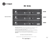
XLS Series XLS 202 Operation Manual XLS 402 XLS 602 Obtaining Other Language Versions: To obtain information in another language about the use of this product, please contact your local Crown Distributor. If you need assistance locating your local distributor, please contact Crown at 574-294-8000. This manual does not include all of the details of design, production, or variations of the equipment. Nor does it cover every possible situation which may arise during installation, operation or maintenance.
XLS Series Power Amplifiers 1) 2) 3) 4) 5) 6) 7) 8) 9) 10) 11) 12) 13) 14) 15) page 2 Read these instructions. Keep these instructions. Heed all warnings. Follow all instructions. Do not use this apparatus near water. Clean only with a dry cloth. Do not block any ventilation openings. Install in accordance with the manufacturer’s instructions. Do not install near any heat sources such as radiators, heat registers, stoves, or other apparatus that produce heat.
XLS Series Power Amplifiers DECLARATION of CONFORMITY Crown International, Inc. Issued By: Crown International, Inc. 1718 W. Mishawaka Road Elkhart, Indiana 46517 U.S.A. Sue Whitfield 574-294-8289 swhitfield@crownintl.
XLS Series Power Amplifiers Table of Contents Important Safety Instructions ................................................2 4 Advanced Features and Options ...................................... 15 Declaration of Conformity ............................................................3 4.1 Protection Systems ........................................................ 15 1 Welcome ................................................................................5 4.1.1 Output Current Limiting..............
XLS Series Power Amplifiers XLS 202 *1 kHz Power 2-ohm Stereo (per channel) 250W 4-ohm Stereo (per channel) 200W 8-ohm Stereo (per channel) 145W 8-ohm Bridge-Mono 400W 4-ohm Bridge-Mono 500W *1 kHz Power: refers to maximum average power in watts at 1 kHz with 0.5% THD.
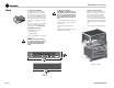
XLS Series Power Amplifiers 2 Setup 2.1 Unpack Your Amplifier Please unpack and inspect your amplifier for any damage that may have occurred during transit. If damage is found, notify the transportation company immediately. Only you can initiate a claim for shipping damage. Crown will be happy to help as needed. Save the shipping carton as evidence of damage for the shipper’s inspection. We also recommend that you save all packing materials so you will have them if you ever need to transport the unit.
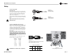
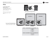
XLS Series Power Amplifiers 2 Setup 2.4 Choose Input Wire and Connectors Crown recommends using pre-built or professionally wired balanced line (two-conductor plus shield), 22-24 gauge cables and connectors. You should use 3-pin male XLR cable ends at the amplifier inputs. Unbalanced line may also be used but may result in noise over long cable runs. Figure 2.3 Balanced Input Connector Wiring Figure 2.3 shows connector pin assignments for balanced wiring, and Figure 2.
XLS Series Power Amplifiers 2 Setup 2.6 Wire Your System 2.6.1 Stereo Mode Using the 5-way Binding Posts Typical input and output wiring is shown in Figure 2.7 INPUTS: Connect input wiring for both channels. OUTPUTS: Maintain proper polarity (+/–) on output connectors. Connect Channel 1 loudspeaker’s positive (+) lead to Channel 1 positive (red) terminal of amp; repeat for negative (–). Repeat Channel 2 wiring as for Channel 1. Figure 2.7 shows how to wire stereo speakers to the 5-way binding posts.
XLS Series Power Amplifiers 2 Setup 2.6.2 Stereo Mode Using the Speakon® Connector There are two ways to wire two speakers in stereo to the amplifier’s Speakon® connector. 1) Wire the two speakers to the same Speakon® connector as shown in Figure 2.8. or Figure 2.8 Speakon® Stereo Wiring Option 1: Wire Two Speakers to One Speakon® Connector 2) Wire speaker 1 to the amplifier’s Speakon® connector, and wire speaker 2 to speaker 1 (Figure 2.9). SPEAKER 1 SPEAKER 2 AMPLIFIER Figure 2.
XLS Series Power Amplifiers 2 Setup 2.6.3 Bridge-Mono Mode INPUTS: Use a custom “Y” adapter cable, wired to split the signal and invert the polarity for the Channel 2 amplifier input as shown in Figure 2.10. We recommend you label the ends of the Y adapter to help make sure to connect the correct end to each amplifier input. Connect the Y adapter between the signal source and each amplifier input (Figure 2.11).
XLS Series Power Amplifiers 2 Setup 2.7 Connect to AC Mains Connect your amplifier to the AC mains power source (power outlet) with the supplied AC power cordset. First, connect the IEC end of the cordset to the IEC connector on the amplifier; then, plug the other end of the cordset to the AC mains. 2.9 Startup Procedure Use the following procedure when first turning on your amplifier: WARNING: The third prong of this connector (ground) is an important safety feature.
XLS Series Power Amplifiers 3 Operation 3.1 Precautions Your amplifier is protected from internal and external faults, but you should still take the following precautions for optimum performance and safety: 1. Before use, your amplifier first must be configured for proper operation, including input and output wiring hookup. Improper wiring can result in serious operating difficulties.
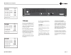
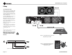
XLS Series Power Amplifiers 3 Operation 3.2 Front Panel Controls and Indicators A. Cooling Vents Front-to-rear forced airflow. D. Power Indicator Green LED indicates amplifier has been turned on and AC power is available. E. Fault Indicator Two black rotary level controls, one for each channel. Yellow LED illuminates when amplifier is in protect mode. Also illuminates briefly during normal power-up when amplifier is first switched on. C. Clip Indicators F.
XLS Series Power Amplifiers 3 Operation 3.3 Back Panel Controls and Connectors G. Power Connector H. Circuit Breaker Provides overload protection. I. Balanced XLR Inputs Two 3-pin female XLR input connectors are provided (one per channel). J. Fans Provide front-to-back forced airflow for cooling. K. 5-Way Binding Post Output Jacks One pair per channel; accept banana plugs, spade lugs or bare wire.
XLS Series Power Amplifiers 4 Advanced Features and Options NOTE: For detailed information about these Crown amplifier features, please consult the Crown Amplifier Application Guide, available on the Crown website at www.crownaudio.com. 4.1.3 Circuit Breaker The high-voltage power supplies of your Crown amplifier are protected by a circuit breaker. The breaker rating varies depending on model and supply voltage as follows: 4.
XLS Series Power Amplifiers 5 Troubleshooting CONDITION: Normal operation. CONDITION: No sound. POSSIBLE REASON: POSSIBLE REASON: • • The amplifier has just turned on and is still in the 4-second turn-on delay. • The amplifier is in “fault” mode. A Fault status can be triggered when one of the amplifier’s protection circuits is activated. First disconnect your speakers from the affected channels(s) one by one to determine if one of the loads is shorted.
XLS Series Power Amplifiers 6 Specifications Minimum Guaranteed Power XLS 202 XLS 402 XLS 602 250W 200W 145W 400W 500W 570W 400W 260W 800W 1,140W 840W 600W 370W 1,200W 1,680W 250W 225W 500W 610W 445W 1,120W 880W 670W 1,760W XLS 202 XLS 402 XLS 602 0.725 1.025 1.26 120 VAC, 60 Hz Units, per channel, both channels driven 1 kHz with 0.5% THD Stereo, 2 ohms (per ch.) Stereo, 4 ohms (per ch.) Stereo, 8 ohms (per ch.
XLS Series Power Amplifiers 6 Specifications Performance XLS 202 XLS 402 XLS 602 Damping Factor (8 ohm): 10 Hz to 400 Hz > 200 > 200 > 200 Crosstalk (below rated power, at 1 kHz at 20 kHz –82 dB –58 dB –82 dB –58 dB –82 dB –58 dB DC Output Offset (Shorted input) Input Impedance (nominally balanced, nominally unbalanced) Load Impedance (Note: Safe with all types of loads) Stereo Bridge Mono Voltage Gain (at maximum level setting) AC Line Voltage and Frequency Configurations Available (± 10%) Con
XLS Series Power Amplifiers 7 AC Power Draw and Thermal Dissipation This section provides detailed information about the amount of power and current drawn from the AC mains by XLS amplifiers and the amount of heat produced under various conditions. The calculations presented here are intended to provide a realistic and reliable depiction of the amplifiers. The following assumptions or approximations were made: Here are the equations used to calculate the data presented in Figures 7.1, 7.2 and 7.
XLS Series Power Amplifiers 7 AC Power Draw and Thermal Dissipation XLS 202 LOAD 2 Ohm Stereo Duty Cycle AC Mains Power Draw (W) 50% 40% 30% 20% 10% 529 427 325 223 121 Current Draw (Amps) 4 Ohm Stereo Thermal Dissipation 120V 230V btu/hr kcal/hr 5.1 4.1 3.1 2.1 1.2 2.6 2.1 1.6 1.1 0.6 953 776 598 420 243 240 196 151 106 61 AC Mains Power Draw (W) 427 346 264 182 101 Current Draw (Amps) 8 Ohm Stereo Thermal Dissipation 120V 230V btu/hr kcal/hr 4.1 3.3 2.5 1.7 1.0 2.1 1.7 1.3 0.9 0.
XLS Series Power Amplifiers 7 AC Power Draw and Thermal Dissipation XLS 602 LOAD 2 Ohm Stereo Duty Cycle AC Mains Power Draw (W) 50% 40% 30% 20% 10% 1359 1093 826 559 293 Current Draw (Amps) 4 Ohm Stereo Thermal Dissipation 120V 230V btu/hr kcal/hr 13.2 10.6 8.1 5.5 2.9 6.9 5.6 4.2 2.8 1.5 1774 1437 1100 763 426 447 362 277 192 107 AC Mains Power Draw (W) 978 788 597 407 216 Current Draw (Amps) 8 Ohm Stereo Thermal Dissipation 120V 230V btu/hr kcal/hr 9.5 7.7 5.8 4.0 2.1 5.0 4.0 3.
XLS Series Power Amplifiers 8 Service Crown amplifiers are quality units that rarely require servicing. Before returning your unit for servicing, please contact Crown Technical Support to verify the need for servicing. list of authorized service centers in your area can be obtained from the Crown website at www.crownaudio.com, or by calling Crown Customer Service. This unit has very sophisticated circuitry which should only be serviced by a fully trained technician.
XLS Series Power Amplifiers 9 Warranty UNITED STATES & CANADA SUMMARY OF WARRANTY 3 AR YE Crown International, 1718 West Mishawaka Road, Elkhart, Indiana 46517-4095 U.S.A. warrants to you, the ORIGINAL PURCHASER and ANY SUBSEQUENT OWNER of each NEW Crown product, for a period of three (3) years from the date of purchase by the original purchaser (the “warranty period”) that the new Crown product is free of defects in materials and workmanship.
XLS Series Power Amplifiers 9 Warranty WORLDWIDE EXCEPT USA & CANADA SUMMARY OF WARRANTY 3 AR YE Crown International, 1718 West Mishawaka Road, Elkhart, Indiana 46517-4095 U.S.A.
XLS Series Power Amplifiers Crown Factory Service Information Shipping Address: Crown Factory Service, 1718 W. Mishawaka Rd.
XLS Series Power Amplifiers THIS PAGE INTENTIONALLY LEFT BLANK page 26 Operation Manual
XLS Series Power Amplifiers NOTES Operation Manual page 27
XLS Series Power Amplifiers page 28 Operation Manual