D E S I G N E D T O L E A D AWR Series Gas-Fired Natural Draft Hot Water Boilers INSTALLATION INSTRUCTIONS These instructions must be affixed on or adjacent to the boiler Models: • AWR038B • AWR070B • AWR105B • AWR140B • AWR175B • AWR210B • AWR245B • AWR280B WARNING: Improper installation, adjustment, alteration, service or maintenance can cause property damage, injury, or loss of life. For assistance or additional information, consult a qualified installer, service agency or the gas supplier.
WARNINGS FOR THE HOMEOWNER FOLLOW ALL INSTRUCTIONS and warnings printed in this manual and posted on the boiler. unless alarms or other safeguards are in place to prevent such damage INSPECT THE BOILER ANNUALLY. To keep your boiler safe and efficient, have a service technician follow the Service checklist near the end of this manual. DO NOT BLOCK AIR FLOW into or around the boiler. Insufficient air may cause the boiler to produce carbon monoxide or start a fire.
Table of Contents I. Product Description ............................................................................... 3 II. Specifications ......................................................................................... 3 III. Before Installing .................................................................................... 4 IV. Locating the Boiler ................................................................................ 4 V. Air for Combustion & Ventilation ................
I Product Description The AWR series boiler is a cast iron gas fired water boiler designed for use in closed forced circulation heating systems. This boiler is a Category I drafthood equipped appliance, which must be vented by natural draft using a lined masonry or listed metal chimney system. An adequate supply of air for combustion, ventilation and dilution of flue gases must be available in the boiler room. II Specifications FIGURE 2.1: GENERAL CONFIGURATION TABLE 2.
III Before Installing 1) Safe, reliable operation of this boiler depends upon installation by a professional heating contractor in strict accordance with this manual and the requirements of the authority having jurisdiction. • In the absence of an authority having jurisdiction, installation must be in accordance with this manual and the National Fuel Gas Code, ANSI Z223.1-latest edition. In Canada, follow CAN/CSA B149.1 (Natural Gas and Propane Installation Code).
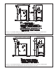
FIGURE 4.1: 38-210MBH MINIMUM CLEARANCE FROM BOILER TO ALL TYPES OF COMBUSTIBLE CONSTRUCTION AND NONCOMBUSTIBLE CEILINGS, WALLS AND DOORS (CLOSET) FIGURE 4.
2) The boiler must be installed on a hard level surface. This surface may be combustible. 3) Do not install this boiler in a location where gasoline or other flammable vapors or liquids will be stored or used. 4) Do not install this boiler in an area where large amounts of airborne dust will be present, such as a workshop. 5) The boiler should be located as close to the chimney as possible. 6) Do not install this boiler over carpeting. This may cause a fire.
rooms together. Repeat for any other connected rooms which do not have doors. Do not add the volume of two rooms separated by a door even if that door is “always left open”. 3) Divide the volume obtained in Step 2 by the input calculated in Step 1. 4) If the result is at least 50 ft3 per 1000BTU/hr, and neither of the conditions described in (6) below are met, normal infiltration should provide adequate fresh air into the boiler room.
350÷135 = 2.59. Since 2.59 is less than 50, there will be an inadequate fresh air supply in the boiler room unless openings are installed between the boiler room and at least one adjacent room. It turns out that the boiler room in this example is adjacent to a full basement which is 20ft x 45ft x 8ft high.
6” MAX 6” MAX FIGURE 5.4: OUTDOOR COMBUSTION AIR METHOD: USING OPENINGS INTO BOILER ROOM 6” MAX 6” MAX FIGURE 5.5: OUTDOOR COMBUSTION AIR METHOD: USING HORIZONTAL DUCTS INTO BOILER ROOM Using the Outdoor Combustion Air Method 1) Openings must be installed between the boiler room and the outdoors or a ventilated space, such as an attic or crawl space, which communicates directly with the outdoors. 2) Two openings are required. The top edge of the upper opening must be within 6 inches of the ceiling.
• If motorized louvers are installed in the openings to the outdoors, they must be interlocked to prevent operation of the fuel burning appliances in the boiler room unless the louvers are open. Mechanical Combustion Air Supply A mechanical system may be used to bring all combustion air to the boiler which meets all of the following requirements: 1) The system must be manufactured specifically for this purpose.
4) Exterior Chimneys - An exterior chimney has one or more sides exposed to the outdoors below the roof line. The National Fuel Gas Code prescribes two conditions under which an exterior chimney may be used: • In some very restrictive cases, this boiler may be vented into an exterior ceramic lined masonry chimney. See the National Fuel Gas Code for information on when exterior chimneys may be used. • An exterior masonry chimney may be used if it is lined with B vent or a listed chimney lining system.
) Installation of the vent damper supplied with this boiler is mandatory. Install vent damper (see Figure 6.2) as follows: a) Open vent damper carton and remove installation instructions. Read the instructions thoroughly before proceeding. Verify that vent damper is same size as draft diverter outlet (Figure 2.1). Unpack vent damper carefully. Do not force closed damper blade. Forcing vent damper closed may result in damaged gear train and void warranty.
f) After it has been determined that each appliance remaining connected to the common venting system properly vents when tested as outlined above, return doors, windows, exhaust fans, fireplace dampers and any other gas-burning appliances to their previous condition of use. g) Any improper operation of the common venting system should be corrected so the installation conforms with the National Fuel Gas Code, ANSI Z223.1.
VIII System Piping WARNING • INSTALL BOILER SO THAT THE GAS IGNITION SYSTEM COMPONENTS ARE PROTECTED FROM WATER (DRIPPING, SPRAYING, RAIN, ETC.) DURING APPLIANCE OPERATION AND SERVICE (CIRCULATOR REPLACEMENT, ETC.). • OPERATION OF THIS BOILER WITH CONTINUOUS RETURN TEMPERATURES BELOW 120°F CAN CAUSE SEVERE HEAT EXCHANGER CORROSION DAMAGE. • OPERATION OF THIS BOILER IN A SYSTEM HAVING SIGNIFICANT AMOUNTS OF DISSOLVED OXYGEN CAN CAUSE SEVERE HEAT EXCHANGER CORROSION DAMAGE.
FIGURE 8.1: STANDARD RELIEF VALVE POSITION FIGURE 8.2: ALTERNATE RELIEF VALVE POSITION FIGURE 8.3: STANDARD BOILER PIPING 5) Automatic Air Vent (Required) - At least one automatic air vent is required. Manual vents will usually be required in other parts of the system to remove air during initial fill. 6) Low Water Cut-Off (factory supplied) This boiler is equipped with a low water cut-off (LWCO) that prevents the boiler from firing if there is inadequate water in the boiler.
7) Manual Reset High Limit (Required by some codes) - This control is required by ASME CSD-1 and some other codes. Install the high limit in the boiler supply piping just beyond the boiler with no intervening valves. Set the manual reset high limit as far above the operating limit setting as possible, but not over 240°F. Wire the control to break the 120 VAC electrical supply to the boiler.
FIGURE 8.5: BOILER BYPASS PIPING FIGURE 8.
directly into the return water. The bypass pipe should be the same size as the supply. The two throttling valves shown are adjusted so that the return temperature rises above 120°F during the first few minutes of operation. A three-way valve can be substituted for the two throttling valves shown. If the circulator is mounted on the supply, the bypass must be on the discharge side of the circulator.
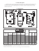
IX Wiring WARNING • ALL WIRING AND GROUNDING MUST BE DONE IN ACCORDANCE WITH THE AUTHORITY HAVING JURISDICTION OR, IN THE ABSENCE OF SUCH REQUIREMENTS, WITH THE NATIONAL ELECTRICAL CODE (ANSI/NFPA 70). • DISCONNECT ELECTRICAL POWER TO THE BOILER AND HEATING SYSTEM BEFORE SERVICING. POSITIVELY ASSURE THAT NO VOLTAGE IS PRESENT. LOCK ELECTRICAL BOXES TO PREVENT SOMEONE FROM INADVERTENTLY RESTORING POWER BEFORE THE HEATING SYSTEM IS SAFE TO OPERATE. • NEVER DEFEAT OR JUMP OUT SAFETY DEVICES.
2. Low Voltage Connections – Low voltage field connections are located as shown in Figure 9.1 and are as follows: a) Heating Thermostat - Connect to a 24 volt thermostat or other “dry contacts” (such as a zone panel end switch) that close upon a call for heat. Follow thermostat manufacturer’s instructions.
FIGURE 9.0: LINE VOLTAGE FIELD CONNECTIONS FIGURE 9.
FIGURE 9.
FIGURE 9.
X Start-up and Checkout WARNING DO NOT LEAVE THE BOILER IN SERVICE IF IT FAILS ANY OF THE FOLLOWING START-UP CHECKS. DOING SO MAY RESULT IN FIRE, EXPLOSION, OR CARBON MONOXIDE (CO) POISONING. WARNING • GAS LEAKS MAY RESULT IN FIRE OR EXPLOSION. • NEVER USE A FLAME TO CHECK FOR GAS LEAKS. • MAKE SURE THAT THE AREA AROUND THE BOILER IS CLEAR AND FREE FROM COMBUSTIBLE MATERIALS, GASOLINE AND OTHER FLAMMABLE VAPORS AND LIQUIDS. • WATER LEAKS MAY CAUSE EXTENSIVE PROPERTY DAMAGE.
12) Check entire gas train for leaks using soap and water or other approved leak detection method while boiler is firing. Fix any leaks found immediately. 13) Run gas valve safety shutdown test. With main burners firing, disconnect ignition cable from ignition module. Both pilot burner and main burners should stop firing. FOR YOUR SAFETY READ BEFORE LIGHTING WARNING: If you do not follow these instructions exactly, a fire or explosion may result causing property damage, personal injury or loss of life. A.
14) Check the manifold pressure and adjust if necessary. To do this, use the following procedure: a) Connect a manometer to the inlet pressure tap on the gas valve (see Figure 10.3). b) Check the line pressure with all gas appliances on and off. The line pressure at the boiler must be within the following limits regardless of what combination of appliances is firing: Line Press (inches w.c.) Natural Gas LP Gas Min. 5.0 11.0 Max. 14.0 13.
FIGURE 10.2: MAIN BURNER FLAME FIGURE 10.1: PILOT BURNER FLAME FIGURE 10.3: GAS VALVE DETAIL Fuel Max. CO2 (%) Min O2 (%) Max CO (PPM) Natural Gas 8.5 6.0 50 PPM Propane 10.0 5.8 50 PPM TABLE 10.
XI Operation A. General Information This boiler uses a proprietary version of the Honeywell S9361A “integrated boiler control” to manage all boiler functions including flame supervision, temperature control, and Circulator operation. This control can operate one or two circulator zones without the use of additional relays. Crown offers several control options that plug into the Option Plug such as an outdoor reset control.
FIGURE 11.1: BOILER CONTROL MENU STATUS MODE: =Current Status (Table 11.2) Press I to enter OPERATING MODE Press and Hold I, ↑, and ↓ for at least 3 sec to enter ADJUSTMENT MODE = Current Boiler Temp.
TABLE 11.2: STATUS CODES Status # Description Meaning No call for heat or DHW OR Call for heat present , but boiler is in thermal purge (See PP on page 32) OR Call for heat/DHW present but boiler temperature is above set point (SP) setting. Damper has opened and control is briefly waiting before starting trial for ignition (pre-purge time is 1.7s). 1 Standby 4 Prepurge 6 7 8 Spark Control is attempting to light pilot Flame proving Control is verifying that the pilot flame is on and stable.
TABLE 11.4: OPERATING MODE PARAMETERS Parameter # bt SP HL HdF Description Meaning Boiler Temperature Current boiler water temperature measured by the control’s sensor. Current target temperature (always the same as the high limit setting unless Crown outdoor reset card option is installed).
C. Using Adjustment Mode WARNING Improper adjustments to control parameters could result in unreliable boiler operation, property damage, personal injury, or loss of life. Adjustments should only be made by a qualified heating technician. A list of parameters which can be changed on this control are shown in Table 11.5. To enter Adjustment mode and change parameters: 1) Press and hold I, ↑, ↓ together for at least 3 seconds. 2) Use I to advance to the parameter which is to be changed.
TABLE 11.6 EXAMPLES OF THERMAL PURGE OPERATION Thermal Purge Settings Boiler Temp at Start Temp Begin Time (Pt) (St) Call Boiler Behavior Example # Call for Heat From Use of DHW Zone 1 T-T N/A 2 min. 140F 130 2 T-T N/A 2 min. 140F 150 3 DHW DHW (dh=dh) 2 min. 140F 150 4 Heat T’stat on DHW Heat (dh=tt2) terminals 2 min.
TABLE 11.7 SUMMARY OF CIRCULATOR BEHAVIOR Thermostat Inputs Parameters DHW 2nd Zone Priority (dh) (Pt) Circulator Outputs T-T “DHW” Use of “DHW” Zone ON OFF DHW dh=dh ON ON OFF OFF ON DHW dh=dh ON OFF ON ON ON DHW dh=dh ON OFF ON ON ON DHW dh=dh OFF ON ON ON OFF DHW dh=dh OFF ON OFF OFF ON DHW dh=dh OFF OFF ON ON OFF Heat dh=tt2 ON or OFF ON OFF OFF ON Heat dh=tt2 ON or OFF OFF ON ON ON Heat dh=tt2 ON or OFF ON ON Heating (Red Circ.
10) Once the ignition module detects the presence of a pilot flame, voltage is applied across the main valve (terminals MV and MV/PV on the valve), opening the valve and establishing main flame. 11) If the water temperature climbs above the high limit setting during the call for heat, the burner will shut down, and the vent damper close, while the Heating Circulator continues to operate.
XII Service and Maintenance WARNING • THE BOILER CONTAINS REFRACTORY CERAMIC FIBER, A POSSIBLE HUMAN CARCINOGEN. USE A NIOSH APPROVED RESPIRATOR WHEN SERVICING HIGH-TEMPERATURE INSULATION AND GASKET MATERIALS. WASH EXPOSED SKIN GENTLY WITH SOAP AND WATER AFTER CONTACT. WASH EXPOSED CLOTHING SEPARATE FROM NORMAL LAUNDRY. • LABEL ALL WIRES PRIOR TO DISCONNECTION WHEN SERVICING CONTROLS. WIRING ERRORS CAN CAUSE IMPROPER AND DANGEROUS OPERATION. VERIFY PROPER OPERATION AFTER SERVICING.
11) Inspect the boiler and hydronic system for leaks. 12) Place the boiler back in operation using the procedure outlined in “Start-up”. Check the pilot line and any other gas piping disturbed during the inspection process for leaks. Heat Exchanger Cleaning Procedure WARNING SOOT DEPOSITS IN THE FLUE PASSAGES ARE A SIGN THAT THE BOILER MAY BE OPERATING AT HIGH CARBON MONOXIDE (CO) LEVELS.
XIII Troubleshooting A. Before Troubleshooting The following pages contain trouble shooting tables for use in diagnosing control problems. When using these tables the following should be kept in mind: 1) This information is only meant to be used by a professional heating technician as an aid in diagnosing boiler problems. 2) Where applicable, follow all precautions outlined in the Section X (Start-up and Checkout).
TABLE 13.
TABLE 13.1 - FAULTS WITHOUT ERROR CODE PRESENT Displayed Codes Problem Possible Cause Burners and Circulator Off • • • • Thermostat/s not calling for heat Loose connection in thermostat, zone valve end switch, or zone panel wiring. Thermostat, zone valve, or zone panel miswired Defective thermostat, zone valve, or zone panel StA 1 tt On Burners Off Circulator On Boiler Warm • • Boiler off on high limit (normal operation) Boiler off on thermal purge (normal operation - See Table 11.
XIV PARTS The following parts may be obtained from any Crown distributor. To find the closest Crown distributor, consult the area Crown representative or the factory at: Crown Boiler Co. Customer Service P.O. Box 14818 Philadelphia Pa. 19134 www.crownboiler.com Main burner orifice shown are for sea level configured boilers. For boilers installed at elevations above 2000 ft, consult the local Crown representative or the factory for the correct main burner orifice.
42
KEY # DESCRIPTION QTY.
44
KEY # QUANTITY PER BOILER OR CROWN PART NUMBER QTY. OR CROWN PN 38 70 105 140 175 25 GAS VALVE (NAT. GAS) ** HONEYWELL VR8204C6000 3507020 1 EA 1 EA 1 EA 1 EA 1 EA 25 GAS VALVE (NAT.
KEY # DESCRIPTION QUANTITY PER BOILER OR CROWN PART NUMBER QTY.
QUANTITY PER BOILER OR CROWN PART NUMBER KEY # DESCRIPTION QTY.
SERVICE RECORD DATE SERVICE PERFORMED
Notes 49
Manufacturer of Hydronic Heating Products P.O. Box 14818 3633 I. Street Philadelphia, PA 19134 www.crownboiler.