
Crown Aruba 5 Installation Manual

38
XIII Troubleshooting
A. Before Troubleshooting
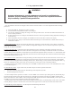
The following pages contain trouble shooting tables for use in diagnosing control problems. When using these tables the
following should be kept in mind:
1) This information is only meant to be used by a professional heating technician as an aid in diagnosing boiler problems.
2) Where applicable, follow all precautions outlined in the Section X (Start-up and Checkout).
3) In general, these tables assume that there are no loose or miswired electrical connections. Before using these tables in-
spect all electrical connections on the boiler to make sure that they are tight. Also, check the wiring on the boiler against
the wiring diagram in Figures 9.2 and 9.3. Ensure that incoming 120 VAC power polarity is correct and that the boiler is
properly grounded. Further, ensure that the control power supply is 24 VAC (minimum 18 VAC to maximum 30 VAC).
4) All controls on the boiler are tested at least once in the manufacturing process and a defective control or component is
generally the least likely cause. Before replacing a component, try to rule out all other possible causes.
5) When checking voltage across at wiring connectors (such as at the vent damper harness plug) be careful not to insert the
meter probes into the metal sockets. Doing so may damage the socket, resulting in a loose connection when the harness
is reconnected.
B. If Display is Blank
1) Check for 24 VAC on transformer secondary connections (screws to which blue and yellow leads are connected). If volt-
age across these screws is between 18 and 30 VAC, possible causes include:
• Loose connection at either plug or transformer end of transformer harness (blue/yellow harness).
• Defective transformer harness
• Defective boiler control
2) If voltage is less than 18VAC at transfer secondary, possible causes include:
• Service switch o
• Trip 120VAC breaker
• Miswired or loose connection in 120VAC boiler circuit.
• Loose connection inside J-box between transformer primary and 120VAC line.
• Defective transformer (possibly caused by short circuit in 24VAC wiring or additional loads connected to the trans-
former in the eld).
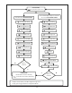
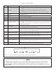
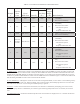
C. If Control Shows Err Code
Use Table 13.0 to help identify and correct the cause of the problem.
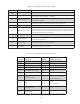
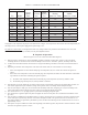
D. If Control Shows StA Code, but Other Problem Present
If no Err Code is observed (even after repeatedly pressing I to cycle through Operation Mode), use Table 13.1 to help iden-
tify and correct the cause of the problem.