
Crown Aruba 5 Installation Manual


4
III Before Installing
1) Safe, reliable operation of this boiler depends upon installation by a professional heating contractor in strict accordance with
this manual and the requirements of the authority having jurisdiction.
• In the absence of an authority having jurisdiction, installation must be in accordance with this manual and the
National Fuel Gas Code, ANSI Z223.1-latest edition. In Canada, follow CAN/CSA B149.1 (Natural Gas and
Propane Installation Code).
• Where required by the authority having jurisdiction, this installation must conform to the Standard for Controls and
Safety Devices for Automatically Fired Boilers (ANSI/ASME CSD-1)-latest edition.
2) Make sure that a properly sized chimney is available which is in good condition. Consult the authority having jurisdiction,
Part VI of this manual, and the National Fuel Gas Code for additional information on venting requirements.
3) Make sure that the boiler is correctly sized:
• For heating systems employing convection radiation (baseboard or radiators) use an industry accepted sizing method
such as the I=B=R Guide RHH published by the Air-Conditioning, Heating and Refrigeration Institute (AHRI).
• For new radiant heating systems refer to the radiant tubing manufacturer’s boiler sizing guidelines.
• For systems that incorporate indirect water heaters, refer to the indirect water heater manufacturer’s instructions for
boiler output requirements.
4) Make sure that the boiler received is congured for the correct gas (natural or LP).
5) Boilers built for installations at altitudes above 2000 ft. require dierent main burner orice. Make sure that the boiler is
congured for use at the correct altitude.
IV Locating the Boiler
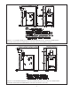
1) Clearances:
• Observe minimum clearances shown below to avoid potential re hazard. Except as noted, these clearances apply to all
combustible construction as well as noncombustible walls, ceilings and doors. Also see Figures 4.1 and 4.2.
Front (38-210MBH) - 6”
Front (245-280MBH) - Alcove
Left Side - 1” (requires relocation of relief valve to right hand side of boiler - Figure 8.2)
Right Side - 4”
Rear (To all combustible construction) - 6”
Rear (38-210MBH To non-combustible wall) - 1”
Rear (245-280MBH To non-combustible wall) - 6”
Top - 24-1/2” Additional Height May Be Required To Maintain 6” Clearance From All Breeching Components
• A 24” service clearance from the jacket is recommended on the left, right, and front of the boiler. These clearances may
be reduced to those shown in Figures 4.1 & 4.2 , however servicing the boiler will become increasingly dicult as these
service clearances are reduced.
WARNING
FAILURE TO OBSERVE THE FOLLOWING LOCATION REQUIREMENTS COULD RESULT
IN A FIRE, EXPLOSION OR CARBON MONOXIDE (CO) HAZARD.