D E S I G N E D T O L E A D BSI Series Gas-Fired Natural Draft Steam Boilers INSTALLATION INSTRUCTIONS These instructions must be affixed on or adjacent to the boiler Models: • BSI207 • BSI069 • BSI103 • BSI241 • BSI138 • BSI276 • BSI172 • BSI311 • BSI346 • BSI380 WARNING: Improper installation, adjustment, alteration, service or maintenance can cause property damage, injury, or loss of life.
WARNINGS FOR THE HOMEOWNER FOLLOW ALL INSTRUCTIONS and warnings printed in this manual and posted on the boiler. unless alarms or other safeguards are in place to prevent such damage INSPECT THE BOILER ANNUALLY. To keep your boiler safe and efficient, have a service technician follow the Service checklist near the end of this manual. DO NOT BLOCK AIR FLOW into or around the boiler. Insufficient air may cause the boiler to produce carbon monoxide or start a fire.
Table of Contents I. Product Description..................................................... 2 II. Specifications.............................................................. 3 III. Before Installing.......................................................... 4 IV. Locating the Boiler...................................................... 4 V. Air for Combustion & Ventilation............................... 5 VI. Venting........................................................................ 9 VII.
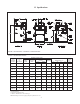
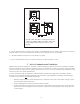
II Specifications FIGURE 1: BSI BOILERS - GENERAL CONFIGURATION TABLE 1: BSI SPECIFICATIONS NATURAL OR LP GAS*** HEATING AHRI NET RATING, CAPACITY STEAM (MBH) (Sq. ft) (MBH) BASIC BOILER MODEL NUMBER OF SECTIONS INPUT (MBH) BSI069 3 69 57 179 43 81.9 BSI103 4 103 85 267 64 82.0 BSI138 5 138 113 354 85 82.0 BSI172 6 172 142 446 107 BSI207 7 207 171 533 BSI241 8 241 199 BSI276 9 276 BSI311 10 BSI346 BSI380 AFUE % DIMENSIONS (in.
III Before Installing 1) Safe, reliable operation of this boiler depends upon installation by a professional heating contractor in strict accordance with this manual and the requirements of the authority having jurisdiction. • In the absence of an authority having jurisdiction, installation must be in accordance with this manual and the National Fuel Gas Code, ANSI Z223.1-latest edition.
FIGURE 2: BSI BOILERS - CLEARANCES TO ALL TYPES OF COMBUSTIBLE CONSTRUCTION AND NONCOMBUSTIBLE CEILINGS, WALLS, AND DOORS. 4) Do not install this boiler in a location where gasoline or other flammable vapors or liquids will be stored or used. Do not install this boiler in an area where large amounts of airborne dust will be present, such as a workshop. 5) The boiler should be located as close to the chimney as possible. 6) Do not install this boiler directly on a surface that may get wet.
For Buildings of Other than Unusually Tight Construction 1) Determine whether the boiler is to be installed in a confined space - A confined space is defined by the National Fuel Gas Code as having a volume less than 50 cubic feet per 1000 BTU/hr input of all appliances installed in that space. To determine whether the boiler room is a confined space: a. b. c. Total the input of all appliances in the boiler room in thousands of BTU/hr. Round the result to the next highest 1000 BTU/hr.
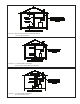
FIGURE 3: BOILER INSTALLED IN CONFINED SPACE, ALL AIR FROM INSIDE FIGURE 4: ALL AIR FROM OUTDOORS, VENTILATED CRAWL SPACE AND ATTIC FIGURE 5: ALL AIR FROM OUTDOORS, VIA VENTILATED ATTIC 7
FIGURE 6: ALL AIR FROM OUTDOORS, USING OPENINGS INTO BOILER ROOM FIGURE 7: ALL AIR FROM OUTDOORS, USING HORIZONTAL DUCTS INTO BOILER ROOM 8
VI Venting Vent installation must be in accordance with local building codes, or the local authority having jurisdiction, or the National Fuel Gas Code, NFPA 54/ANSI Z 223.1. A typical vent installation is illustrated by Figure 8. The components of vent installation are the vent damper (if used), vent connector and chimney.
14) Vent damper installation is mandatory on all sizes from the BSI069 to BSI276. The BSI311 through BSI380 may be ordered with or without vent damper. If supplied, install vent damper (see Figure 9) as follows: a) Open vent damper carton and remove installation instructions. Read the instructions thoroughly before proceeding. Verify that vent damper is same size as draft diverter outlet. See Figure 1. Unpack vent damper carefully. Do not force closed damper blade.
FIGURE 8: BSI BOILER TYPICAL VENT SYSTEM INSTALLATION AND COMPONENTS RIGHT SIDE VIEW FIGURE 9: VENT DAMPER INSTALLATION DETAILS 11
VII Gas Piping Gas piping to the boiler must be sized to deliver adequate gas for the boiler to fire at the nameplate input at a line pressure between the minimum and maximum values shown on the rating plate. For more information on gas line sizing, consult the utility or Chapter 2 of the National Fuel Gas Code. Figure 10 shows typical gas piping connection to the BSI boiler. A sediment trap must be installed upstream of all gas controls.
VIII System Piping CAUTION • INSTALL BOILER SO THAT THE GAS IGNITION SYSTEM COMPONENTS ARE PROTECTED FROM WATER (DRIPPING, SPRAYING, RAIN, ETC.) DURING APPLIANCE OPERATION AND SERVICE (CIRCULATOR REPLACEMENT, ETC.). • OPERATION OF THIS BOILER IN A SYSTEM HAVING SIGNIFICANT AMOUNTS OF DISSOLVED OXYGEN CAN CAUSE SEVERE HEAT EXCHANGER CORROSION DAMAGE.
Piping Installation 1) Remove parts bag from boiler crate. 2) Install safety valve (spindle must be in vertical position) into tapping on boiler left side (see Figure 1) using the 3/4” NPT nipples and elbow supplied. 3) Pipe the discharge of the safety relief valve to a location where water or steam will not create a hazard or cause property damage if the valve opens. The end of the discharge pipe must terminate in an unthreaded pipe.
BOILER MODEL BSI069 BSI103 BSI138 BSI172 BSI207 BSI241 BSI276 BSI311 BSI346 BSI380 MINIMUM PIPE DIA.
IX Indirect Water Heater Piping All BSI series boilers are equipped with tappings to permit the connection of a Crown Mega-Stor, or other indirect water heater. In this type of system, hot boiler water is drawn from below the water line and passed through the heat exchanger in the indirect water heater. This section describes boiler-side piping only. Refer to the indirect water heater instruction manual for domestic water piping.
X Wiring WARNING All wiring and grounding must be done in accordance with the authority having jurisdiction or, in the absence of such requirements, with the National Electrical Code (ANSI/NFPA 70) 1) 120 Volt Wiring - The boiler should be provided with its own 15A branch circuit with fused disconnect. All 120 volt connections are made inside the junction box on the left side of the boiler.
Feeder Wiring for Boilers Equipped with McDonnell & Miller #67 Low Water Cut-offs Figures 14a and 14b show feeder wiring for McDonnell & Miller #101A, McDonnell & Miller WF2-U-24 and Hydrolevel VXT-24 feeders on boilers equipped with #67 low water cutoffs. The following points apply to all feeder wiring to #67 low water cut-offs: • • Use a separate transformer to power the feeder. Do not use the transformer on the boiler. • Do NOT install a jumper between terminals 2 and 3 on the #67 low water cutoff.
CAUTION DO NOT INSTALL JUMPER BETWEEN 2 & 3 ON #67 L.W.C.O. FIGURE 14b: WIRING MCDONNELL & MILLER WF2-U-24 FEEDER OR THREE-WIRE HYDROLEVEL VXT-24 FEEDER TO BOILER EQUIPPED WITH #67 L.W.C.O.
BSI Control System – Sequence of Operation (Refer to Figures 16 & 17 for ladder and connection diagrams) Sequence of Operation, Intermittent Ignition 1) When the boiler is energized, 24 volts is immediately applied to terminals “1” (blue) and “4” (yellow) on the vent damper. Assuming that there is no call for heat, and that the damper switch is in the “automatic” position, the damper will close.
Blocked Vent (“Spill”) Switch - Automatically interrupts burner operation in the event that flue gas spills from the draft diverter opening. This switch is equipped with a reset button which must be pressed to restore normal burner operation. An open blocked vent switch is indicative of a problem with the vent system. If the blocked vent switch opens, the cause of the venting problem must be found and corrected by a qualified gas service technician before the blocked vent switch is reset.
FIGURE 17: WIRING DIAGRAM, INTERMITTENT IGNITION AND McDONNELL & MILLER MODEL #67 LOW WATER CUTOFF 22
NOTE SAFE LIGHTING AND OTHER PERFORMANCE CRITERIA WERE MET WITH THE GAS MANIFOLD AND CONTROL ASSEMBLY PROVIDED ON THE BOILER WHEN THE BOILER UNDERWENT THE TESTS SPECIFIED IN Z21.13.
WARNING FAILURE TO FOLLOW THE FOLLOWING PROCEDURE EXACTLY COULD RESULT IN OVERFIRING OF THE BOILER AND A CARBON MONOXIDE HAZARD. 16) Check the manifold pressure and adjust if necessary. To do this, use the following procedure: a) Connect a manometer to the inlet pressure tap on the gas valve (see Figure 20). b) Check the inlet pressure with all gas appliances on and off.
LIGHTING INSTRUCTIONS FOR BOILERS EQUIPPED WITH HONEYWELL VR8204 AND VR8304 SERIES GAS VALVES FOR YOUR SAFETY READ BEFORE LIGHTING WARNING: If you do not follow these instructions exactly, a fire or explosion may result causing property damage, personal injury or loss of life. If you cannot reach your gas supplier, call the fire department. A. This appliance is equipped with an ignition device which automatically lights the pilot. Do not try to light the pilot by hand. C.
LIGHTING INSTRUCTIONS FOR BOILERS EQUIPPED WITH ROBERTSHAW 7000DERHC SERIES GAS VALVES FOR YOUR SAFETY READ BEFORE LIGHTING WARNING: If you do not follow these instructions exactly, a fire or explosion may result causing property damage, personal injury or loss of life. If you cannot reach your gas supplier, call the fire department. A. This appliance is equipped with an ignition device which automatically lights the pilot. Do not try to light the pilot by hand. C.
FIGURE 19b: MAIN BURNER FLAME - 40mm (“HIGH ALTITUDE”) BURNERS FIGURE 19a: MAIN BURNER FLAME - 1” BURNERS 17) Test thermostat operation while the boiler is running. Turn the thermostat to the lowest setting. Both pilot burner and main burners should stop firing. Raise the thermostat back to the highest setting. The pilot burner and main burners should relight. 18) Verify low water cutoff operation while the boiler is running.
f) Reinstall safety valve and related piping. g) Conduct pH and Alkalinity test of water in the system. The pH reading should be in 7 to 11 range. NOTE When substantial amount of make-up water is used due to lost condensate, or when make-up water is hard or corrosive, water treatment is required. Contact qualified water treatment company for recommended water treatment compounds and procedures.
XII Service and Maintenance On a continuous basis: 1) Keep the area around the boiler free and clear from combustible materials, gasoline, and other flammable vapors and liquids. 2) Keep the area around the boiler and boiler room ventilation openings clear of objects which might obstruct the flow of combustion and ventilation air.
• For McDonnell & Miller #67 low water cut-offs - Remove and inspect switch and float mechanism. Inspect float bowl for mud accumulation. Clean as required. Replace the switch and float mechanism every five years or 100,000 cycles. Consult the McDonnell and Miller #67 manual for any additional maintenance information. Test the low water cut-off before placing the boiler back into service. 13) Allow the boiler to cool to room temperature.
12) Replace the flue collector gasket strips. If desired, RTV silicone sealant with a 500F intermittent duty temperature may be substituted for this rope gasket. The flue collector must be thoroughly sealed to the heat exchanger. 13) Replace the ¼-20 nuts and washers that hold down the flue collector 14) Reattach all the jacket components. 15) Reinstall burners, being careful to put the pilot main burner in its original location. 16) Replace the blocked vent switch.
Notes 32
XIII Troubleshooting The following pages contain troubleshooting charts for use in diagnosing control problems. To use these charts, go to the box marked “Start” at the top of the chart on page 34 or 36 and follow the appropriate path though the chart until a box with a list of possible causes is reached. If the problem is known to be within the ignition system, go directly to the ignition system troubleshooting guide for the boiler on page 38.
Troubleshooting Chart for BSI Boilers Equipped with Hydrolevel CG400A Low Water Cut-offs and Vent Dampers Caution: Read page 33 before attempting to use this chart START Vent damper open? Is there an audible click as R8225 relay pulls in when the thermostat calls for heat? Thermostat calls for heat Y N N N Y 24 volts across blue and yellow wires inside junction box? Is yellow LED lit on LWCO? N 24 volts between P2 and 2 on CG400 LWCO? N 120 volts across black and white transformer leads? Y Y
Main burners light? Do burners shut down when pressure exceeds limit setting? Y N Do burners shut down when water level drops below cut-off point? Y N 24 volts across red damper lead and yellow transformer lead? END N * Defective damper * Defective or loose damper harness * Obstruction in path of damper blade N Y * Defective pressure limit control * Blockage in siphon tube Y 24 volts across standing pilot gas valve terminals or terminals 5&6 on S8600 module? Y *Grounded probe or probe lead
Troubleshooting Chart for BSI Boilers Equipped with McDonnell & Miller #67 Low Water Cut-offs and Vent Dampers Caution: Read page 33 before attempting to use this chart START Vent damper open? Is there an audible click as R8225 relay pulls in when the thermostat calls for heat? Thermostat calls for heat Y Y N N N 24 volts between terminal #1 on 67 LWCO and yellow tranformer connection? N 120 volts across black and white transformer leads? Y 24 volts across blue and yellow wires inside junction
Main burners light? Do burners shut down when pressure exceeds limit setting? Y N Do burners shut down when water level drops below cut-off point? Y N 24 volts across red damper lead and yellow transformer lead? END N * Defective damper * Defective or loose damper harness * Obstruction in path of damper blade N Y * Defective pressure limit control * Blockage in siphon tube Y 24 volts across standing pilot gas valve terminals or terminals 5&6 on S8600 module? Y *LWCO float bowl filled with m
Ignition System Troubleshooting Chart Caution: Read page 33 before attempting to use this chart START (24 volts is present across 24V and 24V (GND) on ignition module but main burners do not light) Spark across ignitor/sensor gap? Y Does spark stop when pilot lights? Y Pilot lights? N N N * Defective ignition module Y Y N N Y * Defective ignition module Y END N 24VAC across terminals MV & MV/PV on module? 24 volts across PV & MV/PV at gas valve? * Defective ignition module 24 volts between
Notes 39
XIV PARTS The following parts may be obtained from any Crown distributor. To find the closest Crown distributor, consult the area Crown representative or the factory at: Crown Boiler Co. Customer Service P.O. Box 14818 Philadelphia PA. 19134 www.crownboiler.com For boilers installed at elevations above 2000 ft, consult the local Crown representative or the factory for the correct main burner orifice.
41
KEY # DESCRIPTION 42 43 44 44 44 44 44 44 45 1" BURNER WITH PILOT BRACKET (Q348 PILOTS) 1" BURNER LESS PILOT BRACKET MANIFOLD (1" BURNERS) NAT GAS ORIFICE (#44 DRILL SIZE) NAT GAS ORIFICE (#47 DRILL SIZE) NAT GAS ORIFICE (#48 DRILL SIZE) LP GAS ORIFICE (#54 DRILL SIZE) LP GAS ORIFICE (#55 DRILL SIZE) LP GAS ORIFICE (#1.25mm DRILL SIZE) GAS VALVE (E.I., NAT GAS) 45 GAS VALVE (E.I., NAT GAS) 45 45 GAS VALVE (E.I., NAT GAS) (ROBERTSHAW 7000DERHC) GAS VALVE (E.I. PILOT, LP GAS) 45 GAS VALVE (E.I.
43
KEY # DESCRIPTION 75 76 77 78 79 80 81 82 83 84 85 86 87 LEFT SIDE JACKET PANEL RIGHT SIDE JACKET PANEL REAR JACKET PANEL TOP JACKET PANEL LOWER FRONT PANEL UPPER FRONT PANEL DIVERTER PANEL VESTIBULE PANEL HORIZONTAL JACKET CLIP VERTICAL JACKET CLIP #10 X 1/2" SHEET METAL SCREW DOOR KNOB 8-32 X 1/4" H.W.H. SCREW IGNITION MODULE (E.I. BOILERS) (NATURAL GAS ONLY) IGNITION MODULE (E.I. BOILERS) (NATURAL OR LP GAS) MODULE BRACKET (E.I. BOILERS) VENT DAMPER GLASS SET FLOAT TYPE L.W.C.O.
45
Appendix A: Knockdown Boiler Assembly Instructions A. Before Installing 1) Thoroughly inspect the cast iron heat exchanger for any shipping damage, i.e. cracks in the castings, broken lugs or punctures due to mishandling. 2) Do not use the heat exchanger if there is any damage to it. 3) Inspect the joints between the sections for openings. Reseal any openings with high temperature silicone sealant.. 4) Keep the base in the shipping carton until it is time to perform the assembly.
FIGURE A1: BASE, HEAT EXCHANGER, FLUE COLLECTOR ASSEMBLY 47
5) Install the left side panel in the same manner as the right side. 6) Attach the front corners of the diverter panel to the side jacket panels using #10 sheet metal screws. 7) Install the horizontal (angle) jacket clips in the front edge of the side jacket panels. Slide this clip through the rectangular slot that is about halfway up the front edge of the side jacket panels and secure with the 8-32 self tapping screws provided.
FIGURE A2: JACKET INSTALLATION 49
F. Electrical Wiring Connections (Also refer to wiring diagrams in Part X of the installation manual) 1) A pre-wired junction box assembly specific to the control package ordered with the boiler has been provided by the factory. 2) Orient the junction box so the black relay, which is mounted to the outside of the junction box, is facing down. 3) Mount the junction box assembly to the right side jacket using the holes provided (See Figure 1 in the installation manual).
FIGURE A3: TAPPING LOCATIONS (SEE TEXT FOR TAPPING USES) 51
Notes 52
Notes 53
Manufacturer of Hydronic Heating Products P.O. Box 14818 3633 I. Street Philadelphia, PA 19134 www.crownboiler.com P/N 980433 11/14 Rev.