
Operating instructions

CROWN BOILER COMPANY
BWF SERIES BOILER
CATEGORY I VENT KIT
INSTALLATION AND OPERATING INSTRUCTIONS
I Product Description
The BWF Category I vent kit is used to vent the BWF series boiler into a Category I (“Chimney”) vent system. This kit
consists of a special box-shaped adapter which is used to connect single wall smoke pipe or “B” vent to the fan discharge
of a BWF boiler. This adapter is equipped with a spill switch designed to shut down the burners and fan in the event of a
vent blockage. When connected to a properly sized and constructed vent system, all parts of the vent system, including
the adapter box, are under negative pressure.
II Before Installing
1) Read the installation instructions provided with the boiler. The instructions provided with the boiler cover all aspects
of the boiler installation except for venting. These instructions cover the installation of the Category I vent kit and
connection of the boiler to a Category I vent system.
2) Vent installation must be in accordance with the latest edition of the National Fuel Gas Code (NFPA54/ANSI Z223.1)
and all applicable local codes:
• Make sure that the boiler can be vented using a suitable chimney in accordance with all applicable codes.
• In the context of the National Fuel Gas Code, the BWF is classified as a Category I fan-assisted appliance only
when this kit is installed. When this kit is not installed, the BWF is classified as a Category III appliance and
must be vented using one of the stainless steel special vent systems shown in the installation manual.
• Make sure that you have the correct vent kit for the size boiler being installed:
BWF061 - BWF128: Crown #650140 (equipped with 5” collar)
BWF162 - BWF-229: Crown #650141 (equipped with 6” collar)
III Vent Kit Installation
1) Screw the four 10-32 studs supplied into the fan flange
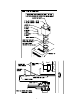
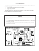
2) Verify that the boiler model number marked on the outlet orifice matches that of the boiler being installed (see Fig. 1).
3) Slip a gasket, the outlet orifice, and the second gasket over the studs as shown in Figure 1.
4) Install the adapter box over the studs with the spill switch facing the right side of the boiler. Secure with the 10-32 nuts
and washers provided.
5) Route the wire harness from the spill switch into the boiler vestibule through knockout “A” shown in Figure 1.
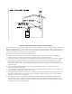
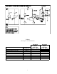
6) Locate the 3/16 male/female quick-connect in the orange wire leading from the high limit. This quick-connect is
located near the right side of the vestibule where the conduit from the high limit enters the vestibule (Figure 2).
7) Unplug this quick connect.
8) Plug the spill switch harness into quick connects opened in Step 7 (also see connection and ladder diagrams).
9) Boiler is now ready to be connected to the vent system.
WARNING
Improper installation, adjustment, alteration, service, or maintenance of this product can cause property damage,
injury, or loss of life. For assistance or additional information, consult a qualified installer, service agency, or the
gas supplier.
PN 980490 Rev. 0
1