P/N: MO-426 (Printed Instruction Manual) Note: This page is not to be included as part of printed hard copy. Overall Specifications: Material: white plain paper Printed text: black Binder: staple upper left corner Individual page specifications: Cover page: printed single-side up The balance of instruction manual pages to be printed utilizing both front and back side of paper.
OIL-FIRED CENTRAL FURNACE Installation, Operation, And Service Manual With Users Information Section Models: CHB68-112 CHC68-96 CLBF68-112 CLBR68-112 c WARNING: • Do NOT store or use gasoline or other flammable vapors and liquids in the vicinity of this or any other appliance. • Improper installation, adjustment, alteration, service, or maintenance can cause a fire or explosion resulting in property damage, personal injury, or loss of life.
Contents SECTION Notice to the Installer PAGE .................................................................................................. 4 INSTALLATION GUIDELINES ...................................................................................... Codes ................................................................................................................. Installation Location ............................................................................................
APPENDIX A: SOURCES FOR REFERENCED STANDARDS ................................... 40 APPENDIX B: ELECTRICAL DIAGRAMS ..................................................................... 41 APPENDIX C: SPECIFICATION SHEETS .................................................................... 43 APPENDIX D: REPLACEMENT PARTS .......................................................................
Notice to the Installer Installation of this oil-fired furnace must be performed by a qualified installer in accordance with all local codes and authorities having jurisdiction. In the absence of local governing codes, installation shall conform to these instructions and to the regulations of the National Fire Protection Association’s Standard for the Installation of Oil-Burning Equipment, NFPA 312001, and the National Electrical Code, ANSI/NFPA 70-2002, or the latest editions thereof.
INSTALLATION GUIDELINES Codes All local codes and regulations take precedence over the instructions in this manual and shall be followed accordingly. In the absence of local codes, this installation must conform to these instructions and to the regulations of the National Fire Protection Association (NFPA) publications, the Standard for the Installation of Oil-Burning Equipment, NFPA 31-2001, and the National Electrical Code, ANSI/NFPA 70-2002, or the latest editions thereof.
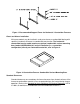
Figure 1: Recommended Support Frame for Horizontal / Counterflow Furnaces Closet and Alcove Installation All furnace models may be installed in a closet or alcove on combustible flooring with specified (standard) clearances to combustible construction. The horizontal / counterflow furnace model requires an optional combustible surface-mounting base (model # CSFB-HC68) for vertical installation (i.e., counterflow configuration) directly on combustible materials, refer to Figure 2.
Accessibility clearances, which are typically greater, may exceed fire protection clearances. Therefore, consider providing at least 24 inches of clearance from the front (and the rear, for lowboy furnaces) of the furnace to obstructions and surfaces for adequate service and maintenance access.
Often, household chemicals contain chloride-bearing compounds. There are many compounds representative of this classification of chemicals. A few common examples are listed below. • • • • • • Cleaning solvents Varnish and paint removers Bleaches Fabric softeners Water softener salt Tile adhesives Avoid storing or using these chemicals within close proximity to the furnace. In addition, avoid storing or using any chemicals, of an unknown and possibly flammable nature, in close proximity to the furnace.
Provide two (2) permanent openings, one (1) located within 12 inches of the floor and one (1) within 12 inches of the ceiling, or roof, of the room. These openings shall allow for direct exchange of air between the room and outdoors. If required, ducting between the room and the outdoors shall be provided.
Chimney Inspection The chimney, vent, or any passageway for the stack gases to flow to the outdoor atmosphere is a very important part of the heating system. No furnace, regardless of the efficiency of the design, can perform satisfactorily when the chimney to which it is connected is inadequate or in poor condition. Any of the following symptoms may indicate a chimney has severe structural damage and is unsuitable for use. • • • • • • Chimney appears to be leaning to the side.
If desired, with the furnace flue elbow turned to the right, the standard furnace top front panel (p/n 52-17346-1) may be replaced with the top front panel from the rear flue lowboy model (p/n 52-17383-1). Refer to Appendix D: Replacement Parts for sketches of these parts. Contact your Crown distributor to purchase this part. All horizontal sections of the vent connector must slope upward not less than ¼ inch per foot from the furnace to the vent termination.
Duct Work and Air Conditioning Design and installation of the duct system should follow the current guidelines of the Air Conditioning Contractors of America (ACCA) or the American Society of Heating, Refrigeration and Air Conditioning Engineers, Inc. (ASHRAE). Refer to the Residential Duct Systems, Manual D, from the ACCA, and the ASHRAE Handbook Fundamentals volume, from ASHRAE, for recommended practices in duct system design and installation.
On the highboy furnace, it is necessary to cut the return air opening in the lower side, or rear, of the casing depending upon the needs of the specific installation, refer to Figure 3. Figure 3: Cutaway view of fan section of a typical highboy furnace. The side casings have each been pre-punched with four (4), square, knockout openings for use in locating the proper position for the return air filter rack.
Electrical Connections NOTICE: All field wiring must conform to local, state, and national installation codes. A disconnecting switch equipped with overcurrent protection rated at 15 A. (e.g. a time delay-type fuse or inverse time, circuit breaker) should be installed in the service line for shutting down and protecting the furnace and electrical system.
The room thermostat should be located on an interior wall in the natural circulating path of the room air. The thermostat should not be installed in a location where it is directly exposed to, • • • cold air infiltration, i.e. drafts from outside openings such as windows and doors, air currents produced by supply air registers, and heat from a nearby source, such as a fireplace, electrical appliances, lamps, solar radiation, a wall enclosing warm air ducts, a chimney, or a flue gas vent.
Nozzle selection (i.e. heating capacity of the furnace) shall be based on a rate of heat loss (heating load) calculation for the building. These calculations should be made according to the manuals provided by the Air Conditioning Contractors of America (ACCA) or the American Society of Heating, Refrigeration and Air Conditioning Engineers, Inc. (ASHRAE).
Figure 4: Side view of correct burner insertion into combustion chamber 4) Push the burner flange gasket (included with the burner) on to the burner mounting plate threaded studs. Seat the gasket against the mounting plate. 5) Using fasteners supplied in the parts bag with each furnace, three (3) 5/16 in. brass hex nuts and three (3) steel flat washers, install and secure the burner to the mounting studs on the burner mounting plate, refer to Figure 5.
the gap between the outer surface of the air tube and the inner wall surface of the combustion chamber opening to provide a seal, keeping hot combustion gases within the chamber. 6) Insert and secure the cable or conduit from the wiring harness in the burner junction box. Snap together the two (2) mating, multipin quick connections, on the wiring harness from the furnace fan center and the wiring harness of the oil burner, inside the burner junction box.
Horizontal / Counterflow Furnace Setup The horizontal / counterflow furnace is shipped from the factory upright for vertical installation (counterflow configuration). If the furnace is to be installed lying down on the right-hand or left-hand side (horizontal configuration), the positions of the oil burner and the fan and limit control thermostat may have to be changed. The horizontal furnace may be turned end for end, or rotated, making the top into the bottom, as shown in Figure 6.
4) When the furnace is installed in the horizontal configuration, the high limit and fan control must also be located in the upper position on the casing when the furnace is placed in the final installed position, refer to Figure 7. If the control must be relocated, remove the cover of the control to gain access to the mounting screws. Remove the mounting screws and the control. Insert the control into the alternate mounting hole in the casing and mark the screw locations.
INITIAL OPERATION OF THE FURNACE Initial Burner Operation c WARNING: To avoid possible explosion, DO NOT attempt to light the burner if: • Oil has accumulated in the base of the combustion chamber. • The furnace is full of fuel vapors. • The combustion chamber is very hot. c CAUTION: The oil burner must be installed and adjusted using recently (within the last year) calibrated combustion instruments by a qualified heating contractor prior to placing the furnace in operation.
7) Measure the oil pump pressure. If required, adjust it to deliver the appropriate pressure for the burner. The oil pump should be set to produce, • • • • 130 PSIG, for the R.W. Beckett model AF burner, 150 PSIG, for the R.W. Beckett model NX burner, 140 PSIG, for the Carlin Combustion model EZ-1HP, and 150 PSIG, for the Riello model 40-F3. NOTICE: On the Riello model 40-F3 burner only, the oil pump port threads conform to British Standard Parallel Pipe (BSPP) thread design.
10) Flue Gas Temperature – The flue gas temperature will vary depending on heat input rate, air temperature rise across the heat exchanger, and air flowrate through the furnace. To prevent excessive water vapor condensation from the flue gases, the gross flue gas temperature should not fall below 330ºF. In addition, if the gross flue gas temperature exceeds 650ºF, the heating efficiency of the furnace will be reduced.
One way to measure the temperature rise across the furnace is to insert temperature measuring devices (e.g. thermometers) into the return air duct and into the supply air duct about 12 inches from the furnace. After the furnace has been firing continually for over 20 minutes, read the temperature difference between the two (2) thermometers. The temperature difference should not exceed 100ºF, nor be less than 70ºF. A temperature rise of 85ºF is considered to be optimum for comfort.
Furnace Limit and Blower Controls All furnaces are equipped with a combined thermostatic high temperature limit and blower (fan) control. The high temperature limit is set such that it does not permit a supply (discharge) air temperature above 200ºF. The thermostatic fan control should be set so the greatest fuel utilization efficiency of the furnace is obtained. Generally, a blower “ON” setting of 130ºF should give the best result.
Room Thermostat Most room thermostats are equipped with user adjustable, or selectable, levels of heat anticipation. This feature helps to reduce the amount of room air temperature overshoot that occurs after a heating cycle. To adjust the heat anticipator, measure the electrical current output of the oil burner primary safety control to the room thermostat. (If measurement is not possible, the value of current output may be marked on the cover of the control).
SERVICE Troubleshooting c WARNING: When testing electrical equipment, always follow standard electrical safety procedures. Before beginning these troubleshooting procedures, always review these basic points. 1) Check for 120 VAC power to the furnace. If there is no voltage, check the disconnecting switch for circuit breaker trip or blown fuses. 2) Make sure the room thermostat is set on the heating mode and is “calling for heat”. 3) Check for sufficient oil supply and that all oil shutoff valves are open.
3) Confirm the room thermostat is wired correctly, set on the “HEAT” mode, and “calling for heat”. 4) For all primary controls, lockout can be confirmed by measuring voltage from the oil primary safety control to the burner motor. If none, depress the oil primary reset button. [On the Honeywell oil primary control, lockout has occurred if the indicator light (an LED) is rapidly flashing; depress the oil primary reset button.
C. Symptom: Burner short cycles on high limit thermostat, but does not “lock out” on oil primary safety control. Items to check: 1) Open dampers or registers in the air distribution system. Clear any duct system restrictions. 2) Inspect and clean all air filters in the air distribution system. 3) Inspect blower for interference with rotation or locked rotor condition. Also, confirm the blower wheel is secured to the fan motor shaft. 4) The fan motor or run capacitor may be damaged.
6) Measure the draft at the point where the vent connector attaches to the heat exchanger flue pipe. With the burner operating, the stack draft should not exceed 0.05 in. W.G. If the stack draft has been adjusted above this value to give the proper overfire draft, the heat exchanger will require cleaning. If there is little or no stack draft, the chimney flue way may require cleaning, the chimney is too restrictive, or a downdraft condition exists. E. Symptom: Furnace blower will not start.
Flame Sensor (“Cad Cell”) Checkout Procedure On the Honeywell oil primary control, to check the electrical resistance of the flame sensor (referred to as a cadmium sulfide photocell, or “cad cell”), depress the reset button on the oil primary safety control while the burner is firing. The oil primary control will report the measured resistance range of the cad cell by flashing the LED (light emitting diode) one (1) to four (4) times. Refer to the oil burner manufacturer’s instructions for further details.
On the Riello 40-F3 burner only, the cad cell is an integral part of the oil primary control. If replacement of the cad cell is required, the entire primary control must be replaced. Replacement Parts Appendix D of this manual contains a list of replacement parts available for these furnaces.
MAINTENANCE Air Filter(s) c CAUTION: To avoid injury from moving parts, hot surfaces, or electrical shock, shut off the power to the furnace and allow the furnace to cool BEFORE removing any furnace access doors to service air filters. Highboy and lowboy furnace models are factory-supplied with a permanent-type, air filter. At least twice a year, remove the air filter(s) for cleaning. Clean a filter by soaking it in water with a mild detergent and then rinsing it with clean water.
NOTICE: A qualified heating contractor MUST inspect the heat exchanger in this furnace at least once a year. If heavy deposits are found, immediate cleaning is required. All heat exchanger surfaces should be as clean as possible for the most efficient operation of the furnace. The heat exchanger may require cleaning after every heating season, as combustion of fuel oil tends to produce soot, particulate matter, and scale, due to corrosion. These materials coat the inner walls of the heat exchanger.
The heat exchanger may also be cleaned through the flue pipe connection. With the furnace turned off and at room temperature, carefully remove the vent connector and the heat exchanger flue pipe, if equipped, to inspect and clean the heat exchanger. The inner radiator of the heat exchanger may be cleaned from the inside of the combustion chamber. This involves removal of the burner and the burner mounting plate from the heat exchanger.
USERS INFORMATION c WARNING: • The area around the furnace should be kept free and clear of flammable vapors, liquids, and material, especially papers and rags. • NEVER burn garbage or refuse in the furnace. NEVER try to ignite oil by tossing burning papers or other material into the furnace. • This oil furnace is designed to burn No. 2 distillate fuel (home heating) oil ONLY. NEVER USE GASOLINE OR A MIXTURE OF OIL AND GASOLINE.
4) This furnace is equipped with an electronic ignition system that automatically lights the burner. DO NOT try to light the burner by hand. 5) Turn on the electric power to the furnace at the disconnecting switch. 6) Adjust the room thermostat to the desired setpoint and set the operating mode, if equipped, to “HEAT”. 7) If the furnace will not operate, call a qualified heating contractor for service.
• Annually, have a bottom sample from the fuel oil tank taken for analysis. If present in excessive quantities, sludge and water should be removed. Fuel oil additives may be of benefit in helping to resolve some problems that are indicated by the analysis. In severe cases, tank cleaning may be required. Consult your fuel oil supplier for recommendations.
Venting System: The furnace flue pipe, vent connector, barometric damper, and chimney should be inspected for: • Signs of excessive rust, corrosion pitting, and holes. • Signs of condensation or moisture leakage (sometimes indicated by soot or condensate streaks). • Evidence of structural damage, and loose or disconnected piping joints. • Presence animal nests. • Free movement of the vane of the barometric damper without binding or interference.
APPENDIX A: SOURCES FOR REFERENCED STANDARDS 1. Air Conditioning Contractors of America 1712 New Hampshire Avenue, N.W. Washington, D.C. 20009 http://www.acca.org/ 2. American Society of Heating, Refrigeration, and Air-Conditioning Engineers, Inc. 1791 Tullie Circle N.E. Atlanta, Georgia 30329 http://www.ashrae.org/ 3. National Fire Protection Association 1 Batterymarch Park Quincy, Massachusetts 02269 http://www.nfpa.
41 Notes: 1. Using wirenuts, connect power supply wire L1 to pigtail marked "1" and wire L2 to pigtail marked "2" in fan center. Connect an earth grounding wire to ground wire terminal in fan center. 2. If any electrical wiring must be replaced, new wiring must have an insulation type rated for 105°C or greater. 3. Use only copper conductors for all field and replacement wiring. 4. For adequate overcurrent protection, maximum acceptable size time delay type fuse or inverse time circuit breaker is 15 A. 5.
42 Notes: 1. Using wirenuts, connect power supply wire L1 to pigtail marked "1" and wire L2 to pigtail marked "2" in fan center. Connect an earth grounding wire to ground wire terminal in fan center. 2. If any electrical wiring must be replaced, new wiring must have an insulation type rated for 105°C or greater. 3. Use only copper conductors for all field and replacement wiring. 4. For adequate overcurrent protection, maximum acceptable size time delay type fuse or inverse time circuit breaker is 15 A. 5.
APPENDIX C: SPECIFICATION SHEETS Crown Furnace Oil-Fired Highboy Furnace Specifications CHB 68-112 Model Heat Input Rate (BTUH): 140000 * 119,000 105,000 84,000 83.6 Nominal Thermal Efficiency (%): Heating Capacity (BTUH): 115000 * 98,000 87,000 70,000 85 Nominal Temp. Rise (deg. F.): 82.4 Minimum AFUE Rating (%): 27.8 Gross Heat Exchange Area (sq. ft.): 58 Casing Height (in.): 22.25 Casing W idth (in): 31 Casing Depth (in.): 6 Nominal Flue Outlet Dia. (in.): 53.
Crown Furnace Oil-Fired Lowboy Furnace Specifications CLBF 68-112 (Front Flue) or CLBR 68-112 (Rear Flue) Model Heat Input Rate (BTUH): 140000 * 119,000 105,000 84,000 84.2 Nominal Thermal Efficiency (%): Minimum Heating Capacity (BTUH): 114000 * 98,000 87,000 70,000 85 Nominal Temp. Rise (deg. F.): 82.0 Minimum AFUE Rating (%): 27.8 (front flue) / 30.0 (rear flue) Gross Heat Exchange Area (sq. ft.) ** : 41.5 Casing Height (in.): 22.25 Casing W idth (in): 47 Casing Depth (in.): 6 Nominal Flue Outlet Dia.
Crown Furnace Oil-Fired Horizontal/Counterflow Furnace Specifications CHC 68-96 Model Heat Input Rate (BTUH): 119,000 105,000 84,000 84.2 Nominal Thermal Efficiency (%): Minimum Heating Capacity (BTUH): 98,000 86,000 69,000 85 Nominal Temp. Rise (deg. F.): 82.0 Minimum Efficiency Rating (AFUE): 27.8 Gross Heat Exchange Area (sq. ft.): 22.25 (in horizontal configuration) Casing Height (in.): 61.25 [in counterflow (vertical) configuration] 61.25 (in horizontal configuration) Casing W idth (in.): 22.
APPENDIX D: REPLACEMENT PARTS Highboy Model 46
Lowboy Front Flue Model 47
Lowboy Rear Flue Model 48
Horizontal/Counterflow Model 49