CWD Series Gas-Fired Direct Vent Hot Water Boilers INSTALLATION INSTRUCTIONS These instructions must be affixed on or adjacent to the boiler Models: • CWD060 • CWD083 • CWD110 • CWD138 • CWD165 • CWD193 • CWD220 • CWD245 WARNING: Improper installation, adjustment, alteration, service or maintenance can cause property damage, injury, or loss of life. For assistance or additional information, consult a qualified installer, service agency or the gas supplier.
TABLE OF CONTENTS I II III IV V VI VII VIII IX X XI XII XIII Product Description Specifications Before Installing Locating the Boiler Air for Combustion and Ventilation Venting Vent System Design Vent System Assembly Gas Piping System Piping Wiring CB502 Control System R8285 Control system Start-up and Checkout Service and Maintenance Troubleshooting Parts Appendix A:Special Requirements for Side-Wall Vented Appliances in the Commonwealth of Massachusetts 2 1 1 2 2 4 9 9 22 32 33 38 38 44 48 52 57 65 7
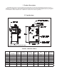
I Product Description The CWD series boiler is a cast iron gas fired boiler designed for use in forced hot water heating systems. It is is a low pressure boiler intended for use in closed heating systems with water temperatures under 240F. This boiler may be vented either vertically or horizontally with combustion air supplied from either outdoors or (under certain conditions) indoors. It is ideal for use in installations where a reliable source of clean indoor combustion air cannot be guaranteed.
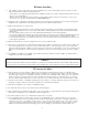
III Before Installing 1) Safe, reliable operation of this boiler depends upon installation by a professional heating contractor in strict accordance with this manual and the authority having jurisdiction. • In the absence of an authority having jurisdiction, installation must be in accordance with this manual and the National Fuel Gas Code, ANSI Z223.1.
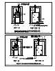
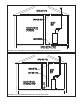
FIGURE 2a: CLEARANCES WHEN BOILER IS DIRECT VENTED (OUTDOOR COMBUSTION AIR IS USED) FIGURE 2b: CLEARANCES WHEN COMBUSTION AIR IS OBTAINED FROM BOILER ROOM 33
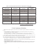
TABLE 2: CLEARANCES FROM VENT PIPING TO COMBUSTIBLE CONSTRUCTION MINIMUM CLEARANCE TO COMBUSTIBLE MATERIAL TYPE OF VENT PIPE PIPE DIRECTION ENCLOSURE HEAT FAB SAF-T VENT PROTECH FASNSEAL PROTECH FASNSEAL W2 METAL-FAB CORR/GUARD VERTICAL OR HORIZONTAL AT LEAST ONE SIDE OPEN, COMBUSTIBLE MATERIAL ON A MAXIMUM OF THREE SIDES HEAT FAB SAF-T VENT PROTECH FASNSEAL Z-FLEX Z-VENT III METAL-FAB CORR/GUARD HORIZONTAL OR VERTICAL WITH OFFSETS ENCLOSED ON ALL FOUR SIDES HEAT FAB SAF-T VENT PROTECH FASNSEAL Z-
Step 2: Determine whether the boiler is to be installed in a confined space A confined space is defined by the National Fuel Gas Code as having a volume less than 50 cubic feet per 1000 BTU/hr input of all appliances installed in that space. To determine whether the boiler room is a confined space: 1) Total the input of all appliances in the boiler room in thousands of BTU/hr. Round the result to the next highest 1000 BTU/ hr. 2) Find the volume of the room in cubic feet.
Step 5: If Indoor Combustion Air is Used, Provide Air as Follows: 1) Buildings of other than unusually tight construction: Unconfined Space– Natural infiltration into the boiler room will normally provide adequate air for combustion and ventilation without additional louvers or openings into boiler room. Confined Space – Provide two openings into the boiler room, one near the floor and one near the ceiling.
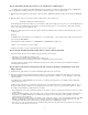
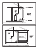
FIGURE 4: ALL AIR FROM OUTSIDE USING VENTILATED CRAWL SPACE AND ATTIC FIGURE 5: ALL AIR FROM OUTSIDE USING VENTILATED ATTIC 77
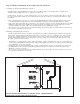
FIGURE 6: ALL AIR FROM OUTSIDE USING OPENINGS INTO BOILER ROOM FIGURE 7: ALL AIR FROM OUTSIDE USING HORIZONTAL DUCTS INTO BOILER ROOM 88
VI Venting WARNING Failure to vent this boiler in accordance with these instructions could result in unreliable boiler operation, severe damage to the boiler or property, or unsafe operation: * Do not attampt to vent this boiler with galvanized, PVC, or any other vent system not listed in Table 4. * Do not attempt to mix components from different approved vent systems. * Do not install a barometric damper or drafthood on this boiler.
TABLE 3a: SUMMARY OF HORIZONTAL VENTING OPTIONS VENT OPTION # 1 CLASSIFICATION USED IN THIS MANUAL ILLUSTRATED IN FIGURE HORIZONTAL DIRECT VENT 2 HORIZONTAL DIRECT VENT 3 (RESERVED FOR FUTURE USE) 4 HORIZONTAL DIRECT EXHAUST 5 HORIZONTAL DIRECT EXHAUST 8a OR 8b 8a OR 8b 9 9 VENT PIPE STRUCTURE PENETRATION WALL WALL WALL WALL AIR INTAKE PIPE STRUCTURE PENETRATION WALL WALL N.A. N.A. 3” 4” 3” 4” AIR INTAKE PIPE SIZE 4” 4” N.A. N.A.
FIGURE 8a: HORIZONTAL DIRECT VENTING USING SEPARATE TERMINALS (VENT OPTIONS 1-2) FIGURE 8b: HORIZONTAL DIRECT VENTING USING COAXIAL TERMINAL (VENT OPTIONS 1-2) 11 11
FIGURE 9: HORIZONTAL DIRECT EXHAUST VENT SYSTEM (VENT OPTIONS 4,5) 2) Maximum Vent and Air Intake Lengths - The maximum length of the vent air intake piping depends upon the vent option selected, the vent pipe size, and the boiler size. See Table 3 for the maximum vent length. In addition to the maximum length of piping shown in Table 3, the following fittings may also be used: • • • • Horizontal Vent Systems: One 90 deg. elbow Vertical Vent Systems: Two 90 deg.
3) Permitted Terminals for Horizontal Venting (Vent Options 1 - 5) - Table 3a shows permitted types of terminals for both the vent and air inlet systems. On horizontal direct vent systems using 4” air inlet pipe (Vent Options 1 and 2), the following Crown co-axial terminals may be used. These terminals have the advantage of requiring only one wall penetration.
TABLE 3b: SUMMARY OF VERTICAL VENTING OPTIONS VENT OPTION # CLASSIFICATION USED IN THIS MANUAL 6 VERTICAL DIRECT VENT ILLUSTRATED IN FIGURE VENT PIPE STRUCTURE PENETRATION AIR INTAKE PIPE STRUCTURE PENETRATION 7 VERTICAL DIRECT VENT 8 (RESERVED FOR FUTURE USE) 9 VERTICAL DIRECT EXHAUST 10 VERTICAL DIRECT EXHAUST 10 10 11 11 ROOF ROOF ROOF ROOF ROOF OR WALL ROOF OR WALL N.A. N.A. 3” 4” 3” 4” AIR INTAKE PIPE SIZE 4” 4” N.A. N.A.
FIGURE 10: VERTICAL NON-COAXIAL DIRECT VENT SYSTEM (VENT OPTIONS 6, 7) FIGURE 11: VERTICAL DIRECT EXHAUST SYSTEM (VENT OPTIONS 9, 10) 15 15
TABLE 3c : SUMMARY OF VERTICAL COAXIAL VENTING OPTIONS VENT OPTION # CLASSIFICATION USED IN THIS MANUAL 11 VERTICAL COAXIAL DIRECT VENT 12 VERTICAL COAXIAL DIRECT VENT 13 VERTICAL COAXIAL DIRECT VENT ROOF ROOF ROOF AIR INTAKE PIPE STRUCTURE PENETRATION ROOF ROOF ROOF VENT PIPE SIZE 3” 3” 4” AIR INTAKE PIPE SIZE (NON-COAXIAL SECTION) AIR INTAKE PIPE SIZE (COAXIAL SECTION) CWD060 - CWD138 4” 4” 4” 5” 5” 7” 47 FT 47 FT 47 FT MAXIMUM VENT PIPE LENGTH VENT PIPE STRUCTURE PENETRATION CW
FIGURE 12: VERTICAL COAXIAL DIRECT VENT USING CROWN #500005 VENT KIT (VENT OPTION 11) FIGURE 13: VERTICAL COAXIAL DIRECT VENT USING HEAT FAB SAF-T VENT SC (VENT OPTIONS 12, 13) 17 17
TABLE 4: PERMISSIBLE VENT SYSTEMS AND PRINCIPLE VENT COMPONENTS MANUFACTURER VENT SYSTEM SAF-T VENT EZ SEAL SIZE CONDENSATE TRAP WALL THIMBLES 3 9321 (NOTE 3) 7393GC 7393GCS 5391CI 4 9421 (NOTE 3) 7493GC 7493GCS 5491CI ELBOW: 7414TERM TEE: 7490TEE 3 SC03DRN (NOTE 3) SC03FS SC03FSA ELBOW (NOTE 5): SC03HT + 7314TERM TEE (NOTE 5): SC03HT + 7390TEE 4 SC04DRN (NOTE 3) SC04FS SC04FSA ELBOW (NOTE 5): SC04HT + 7414TERM TEE (NOTE 5): SC04HT + 7490TEE 3 FSHDT3 FSWT3 ELBOW: FSELB9003 + FSBS3 TE
12) Vertical and horizontal sections of piping must be properly supported. See vent system manufacturer’s instructions for more information. 13) Non-coaxial vent piping must be accessible for periodic inspection. 14) Fire stops and wall thimbles – Use fire stops where required by code or by the vent system manufacturer. Consult vent system manufacturer’s literature for information on suitable fire stops. 15) Supports - Vertical and horizontal sections of vent pipe must be properly supported.
FIGURE 14: HORIZONTAL TERMINAL OFFSETS FIGURE 15a: LOCATION OF DIRECT VENT TERMINAL RELATIVE TO WINDOWS, DOORS, GRADE 20 20
FIGURE 15b: LOCATION OF DIRECT EXHAUST TERMINAL RELATIVE TO WINDOWS, DOORS, GRADE FIGURE 15c: LOCATION OF VENT TERMINAL RELATIVE TO METERS AND FORCED AIR INLETS FIGURE 15d: POSITIONING VENT TERMINAL UNDER OVERHANGS 21 21
FIGURE 16: USE OF CONDENSATE TRAPS C. Vent / Intake System Assembly 1) General Assembly Notes: a) Where the use of “silicone” is called for in the following instructions, use GE RTV 106 for the vent collar and coaxial terminal. Air inlet piping sections are sealed with any general-purpose silicone sealant such as GE RTV102. PVC air inlet piping sections are connected with PVC cement. b) Longitudinal welded seams should not be placed at the bottom of horizontal sections of exhaust pipe.
TABLE 6: FAN OUTLET ORIFICE BOILER MODEL ORIFICE PART # CWD060 620133 CWD083 650136 CWD110 620135 CWD138 620136 CWD165 620137 CWD193 620138 CWD220 620139 CWD245 650138 FIGURE 17: INSTALLATION OF FAN OUTLET ORIFICE 3) Optional Coaxial Terminal Installation – If the optional coaxial terminal is used, it should be installed in the wall before vent assembly is started.
FIGURE 18a: CROWN COAXIAL TERMINAL EXPLODED VIEW FIGURE 18b: CROWN COAXIAL TERMINAL ASSEMBLY 24 24
j) Attach the intake tee to the end of the straight section protruding from the inside wall. Use the procedure described in (d) to clean and assemble these parts. k) If the inside terminal section is not supported by the wall through which it passes, install additional supports or bracing to support the terminal. Bracing in contact with the coaxial section of the terminal may be combustible.
5) Assembly of Z-Flex Z-Vent III: a) General Notes: • Non-expanded ends of SVE Series III piping sections may be cut using aviation snips or a 24 thread per inch hacksaw. File or sand the cut end smooth before assembling. Expanded ends may be cut to adapt the SVE series III to the vent collar or Crown coaxial terminal. See the following instructions. • Support horizontal piping sections at intervals of 48” or less. • Vertical venting systems must be supported by at least one Z-Flex fire stop.
6) Assembly of Heat Fab Saf-T Vent EZ Seal: a) Saf-T Vent General Notes: These instructions cover the installation of Saf-T Vent EZ Seal. Saf-T Vent EZ Seal piping has integral gaskets installed in the female ends of the pipe which seal the joints. • In general, Saf-T Vent pipe sections may not be cut. Exceptions to this are the Saf-T Vent slip connector and connections to the boiler vent collar and Crown coaxial terminal.
manufacturer’s instructions before operating the boiler. 7) Assembly of Heat Fab Saf-T Vent SC - On CWD Boiler installations where Saf-T Vent SC is used, some Saf-T Vent EZ Seal (single wall pipe) will always be required between the boiler and the Saf-T Vent SC. Install this pipe as described above.
8) Assembly of Protech FasNSeal a) FasNSeal General Notes: • • • • Do not cut 4” FasNSeal pipe. Consult FasNSeal instructions for method of cutting other 3” pipe. Orient FasNSeal vent components so that the arrows on the piping labels are in the direction of flue gas flow. Support horizontal piping sections at intervals of 6 feet or less. Vertical venting systems must be supported by at least one FasNSeal support. An additional vertical support is required after any offset.
11) Assembly of Vertical Coaxial Vent System Using Crown #500005 Coaxial Vent Kit (Vent Option #11) a) Start by installing the “B” vent piping. Install and assemble this piping in accordance with the “B” vent manufacturer’s instructions. Seal the joints between sections of “B” vent with GE RTV 106 or Dow 732 RTV sealant. Consult the “B” vent manufacturer’s instructions for the clearance to combustibles (typically 1”) as well as for fire stop and support requirements.
FIGURE 23: INSTALLATION OF VENT SUPPORT PROVIDED IN CROWN #500005 VERT.
VII Gas Piping Gas piping to the boiler must be sized to deliver adequate gas for the boiler to fire at the nameplate input at a line pressure between the minimum and maximum values shown on the rating plate. For more information on gas line sizing, consult the utility or the National Fuel Gas Code. Figure 25 shows typical gas piping connections to the CWD boiler. A sediment trap must be installed upstream of all gas controls.
VIII System Piping CAUTION • Install boiler so that the gas ignition system components are protected from water (dripping, spraying, rain, etc) during appliance operation and service (circulator replacement, etc). • Operation of this boiler with continuous return temperatures below 120F can cause severe heat exchanger corrosion damage. • Operation of this boiler in a system having significant amounts of dissolved oxygen can cause severe heat exchanger corrosion damage.
8) Flow control valve (Required under some conditions) – The flow control valve prevents flow through the system unless the circulator is operating. A flow control valve may be necessary on converted gravity systems to prevent gravity circulation. Flow control valves are also used to prevent “ghost flows” in circulator zone systems through zones that are not calling for heat.
FIGURE 26: BASIC PIPING FIGURE 27: INDIRECT WATER HEATER BOILER-SIDE PIPING 35 35
FIGURE 28: BYPASS PIPING FIGURE 29: ISOLATION OF BOILER FROM SYSTEM WITH HEAT EXCHANGER 36 36
FIGURE 30: CHILLER PIPING 37 37
IX Wiring The CWD Series boiler is offered with two different types of control systems: • CB502 Control System - Basic operation of the boiler is controlled with a “CB502 control” (Crown part #42-502) located in the left side of the boiler vestibule. This device controls one or two circulator zones without the use of additional controls and includes LEDs to show the status of the circulators, inducer, and other boiler controls.
FIGURE 31: CB502 CONTROL SYSTEM - SINGLE ZONE FIELD WIRING FIGURE 32: CB502 CONTROL SYSTEM - FACTORY SWITCH / JUMPER CONFIGURATION 39 39
B. CB502 System - Wiring Variations 1) Two Circulator Zones – Figure 33 shows wiring for two circulator zones. The second zone may be either an indirect water heater or a heating zone. No additional electrical controls are required to operate two circulator zones with a standard CWD boiler. 2) Hybrid Zone Valve/Circulator Zone System using Honeywell V8043Fs – The system shown in Figure 34 is useful when zone valves are to be used for space heating zones but not the indirect water heater zone.
FIGURE 33: CB502 CONTROL SYSTEM - FIELD WIRING FOR TWO CIRCULATOR ZONES FIGURE 34: CB502 CONTROL SYSTEM - FIELD WIRING FOR HYBRID CIRCULATOR/ZONE VALVE SYSTEM 41 41
FIGURE 35: CB502 CONTROL SYSTEM - INTERNAL LADDER DIAGRAM 42 42
FIGURE 36: CB502 CONTROL SYSTEM - INTERNAL CONNECTION DIAGRAM 43 43
D. R8285 Control System - Single Zone Wiring 1) Line Voltage (120 VAC) Connections (Fig 37) – The line voltage connections are located in the junction box under the R8285 fan center on the right side of the boiler. • Black – Line voltage “hot” • White – “Neutral” for boiler and circulators • Green – Ground connection 2) The circulator is factory wired. If a different circulator is wired to the boiler, its full load current draw must not exceed 12A.
FIGURE 37: R8285 CONTROL SYSTEM - SINGLE ZONE FIELD WIRING FIGURE 38: R8285 CONTROL SYSTEM - FIELD WIRING FOR TWO CIRCULATOR ZONES 45 45
FIGURE 39: R8285 CONTROL SYSTEM - ZONE VALVE FIELD WIRING FIGURE 40: R8285 CONTROL SYSTEM - INTERNAL LADDER DIAGRAM 46 46
FIGURE 41: R8285 CONTROL SYSTEM - INTERNAL CONNECTION DIAGRAM 47 47
X Start-up and Checkout WARNING • Never attempt to fill a hot empty boiler. • Never use a flame to check for gas leaks. • Make sure that the area around the boiler is clear and free from combustible materials, gasoline, and other flammable vapors and liquids. • If antifreeze is used in the system, it must be a nontoxic type such as propylene glycol.
FOR YOUR SAFETY READ BEFORE OPERATING WARNING: If you do not follow these instructions exactly, a fire or explosion may result causing property damage, personal injury or loss of life. A. This appliance is equipped with an ignition device which automatically lights the pilot. Do not try to light the pilot by hand. If you cannot reach your gas supplier, call the fire department. C. Use only your hand to push in or turn the gas control knob. Never use tools.
WARNING Failure to follow the following procedure exactly could result in over-firing of the boiler and a carbon monoxide hazard. 12) Check the manifold pressure and adjust if necessary. To do this, use the following procedure: a) Connect a manometer to the line pressure tap on the gas valve (see Figure 44). b) Check the line pressure with all gas appliances on and off.
FIGURE 44: GAS VALVE FIGURE 45: MEASURING MANIFOLD PRESSURE 51 51
XI Service and Maintenance The following routine maintenance should be performed on an annual basis: 1) Turn off electrical power and gas supply to the boiler. 2) Remove the burner tray. To do this: a) Remove the intake cover. b) Remove the four Allen head screws holding the elbow flange onto the gas valve. c) Remove the three 10-32 screws holding the manifold gasket plate to the intake box. d) Remove the four 5-16 nuts holding the burner tray in the boiler.
Heat Exchanger Cleaning Procedure WARNING Soot deposits in the flue passages are a sign that the boiler may be operating at high carbon monoxide (co) levels. After cleaning the boiler of soot deposits, check the CO level in the flue gas to insure that the boiler is operating properly. If it is necessary to check CO, use a combustion analyzer, or other instrument which is designed to measure CO in flue gas.
16) Set the flue collector onto the block and press down so that the flue collector is set into the silicone applied in the previous step. 17) Slide the flue collector lugs back into position and retighten the ¼-20 bolts. DO NOT OVER TIGHTEN. 18) Apply a bead of silicone around the outside of the joint between the heat exchanger and the flue collector. 19) Reattach all the jacket components. 20) Reconnect the pressure switch tubes (see Figure 46 for correct tubing orientation). 21) Reconnect the fan.
TABLE 7: PRESSURE SWITCH SETTINGS ALTITUDE CROWN PN MAKE SETTING* (inches w.c.) BREAK SETTING* (inches w.c.) SEA LEVEL - 5200 ft 620009 1.26 1.16 ABOVE 5200 ft 620010 1.10 1.00 *Settings shown are based on “plus tolerance” - actual setting may be lower.
FIGURE 46b: MEASURING PRESSURE ACROSS PRESSURE SWITCH 56 56
XII Troubleshooting The following pages contain troubleshooting charts for use in diagnosing control problems. If troubleshooting a CB502 control system, go to the box marked “Start” at the top of the chart on page 58 and follow the appropriate path though the chart until a box with a list of possible causes is reached.
N START (No call for heat from either zone) PWR LED On? Call from "HEAT 1" zone Y "HEAT 1" Circulator start? N N Y 120 volts across black and white transformer primary leads ? N HEAT LED On? N *Defective transformer harness *Defective CB502 N 120 volts across red and white circulator leads? Y Y Y N Y 24volts transformer secondary? Y "DHW/H2" zone used? 24V across "HEAT 1" T and T N Y * Loose connection between boiler J-box circ.
Call for heat from "DHW/H2" zone "DHW/H2" circulator start? Y Continued on next page N N DHW LED On? Y 24V across "DHW/H2" T and T Y N Defective CB502 board Y 120 volts across blue and white circulator leads? N *Loose connection between boiler J-box and circ * Loose connection in t'stat or zone valve end switch wiring * Defective t'stat or zone valve end switch * T'stat or zone system miswired-consult zone valve or t'stat manufacturer's instructions.
Continued from previous page LIMIT LED on? N * Missing or loose "RESET CONTROL" jumper *Missing or loose "CN1" jumper *Defective CB502 board 24V between brown lead on limit and yellow lead on transformer? N Y Fan On? Y PRESS LED on? N FAN LED on? N Y N Y * Boiler water temp over L4080D setpoint *Defective L4080D N * Kinked or blocked vacuum switch tubing * Defective vacuum switch 24 volts present across yellow transformer lead and red lead on pressure switch? 24 volts present across yello
Wait 30 seconds (prepurge) Pilot light? Main burners light? Y Y N N Do burners shut down before gauge temp exceeds high limit setting +15F? Y N 24 volts between 24V and 24V (GND) on ign.
START Induced draft fan start? Y Circulator start? Wait 30 seconds (prepurge) Y N N Unplug fan and check for 120 volts across black and white connections on female half of plug.
END Pilot light? Y Main burners light? Y Do burners shut down before gauge temp exceeds high limit setting +15F? N N Y N 24 volts between 24V and 24V (GND) on ign. module? Y See "Intermittent Ignition System Troubleshooting Chart" on page 64.
START (24 volts is present across 24V and 24V (GND) on Ignition Module, 30 second prepurge period has passed) Pulsing Spark across ignitor/sensor gap? Y Pilot lights? IMPORTANT: ALL PILOT TROUBLESHOOTING ON THIS CHART MUST BE PERFORMED AFTER THE 30 SECOND PREPURGE HAS ENDED AND BEFORE THE END OF THE 90 SECOND TRIAL FOR IGNITION PERIOD. Does spark stop when pilot lights? Y N Main burner lights? Y Y END N N N 24 volts across terminals PV & MV/PV at module? Y * Module is in soft lockout.
XIII PARTS The following parts may be obtained from any Crown distributor. To find the closest Crown distributor, consult the area Crown representative or the factory at: Crown Boiler Co. Customer Service P.O. Box 14818 Philadelphia Pa. 19134 www.crownboiler.com Main burner orifice shown are for sea level configured boilers. For boilers installed at elevations above 2000 ft, consult the local Crown representative or the factory for the correct main burner orifice.
BLOCK, BASE, FLUE COLLECTOR COMPONENTS KEY DESCRIPTION PART # OR QTY. PART # OR QTY.
67 67
BURNER TRAY COMPONENTS KEY 50 51 52 53 54 55 56 56 56 56 57 58 59 60 60 60 60 61 62 63 64 64 65 66 DESCRIPTION FRONT FIREDOOR FRONT FIREDOOR INSULATION INSULATION SUPPORT BRACKET MICA SIGHT GLASS 1/8 ALUMINUM POP RIVET BURNER MANIFOLD #49 ORIFICE (SEA LEVEL, NAT GAS) #50 ORIFICE (SEA LEVEL, NAT GAS) #56 ORIFICE (SEA LEVEL, LP GAS) #57 ORIFICE (SEA LEVEL, LP GAS) MANIFOLD GASKET MANIFOLD GASKET PLATE 3/4” 90 DEGREE FLANGE HONEYWELL VR8204C2328 GAS VALVE (NAT GAS) HONEYWELL VR8304P2342 GAS VALVE (NAT GAS) HO
69 69
JACKET COMPONENTS KEY 80 81 82 83 84 85 86 87 88 89 90 91 92 DESCRIPTION VESTIBULE PANEL LARGE PLASTIC BUSHING FAN COVER PLATE #10 X 1/2 SHEET METAL SCREW LH JACKET PANEL RH JACKET PANEL REAR JACKET PANEL PLASTIC BUSHING CONTROL PANEL TOP JACKET PANEL CWD FRONT JACKET PANEL DOOR KNOB 8-32 X 1/4 MACH.
71 71
COMMON CONTROLS & TRIM KEY * 100 101 102 103 * 104 105 105 106 111 112 113 114 115 116 117 118 119 120 * PART# OR QTY DESCRIPTION 1/8” SILICONE TUBING HONEYWELL L4080D LIMIT TRIDICATOR GAUGE UT IGNITION MODULE 1003-626A MODULE BRACKET INTERMITTENT IGNITION HARNESS 4X4 JUNCTION BOX SEA LEVEL PRESSURE SWITCH (ALL SIZES) PRESSURE SWITCH (AS NEEDED ABOVE 5200FT) #8 X1/2 SHEETMETAL SCREWS 1 1/2 X 1 1/4 BLACK 90 DEGREE ELBOW ISOLATION FLANGE SET TACO 007 CIRCULATOR 3/4” X 5” NIPPLE 3/4” 90 DEGREE ELBOW 3/4” CLO
73 73
Appendix A: Special Requirements For Side-Wall Vented Appliances In The Commonwealth of Massachusetts IMPORTANT The Commonwealth of Massachusetts requires compliance with regulation 248 CMR 4.00 and 5.00 for installation of side-wall vented gas appliances as follows: 1.
75 75
CROWN Boiler Co Manufacturer of Hydronic Heatings Products P.O. Box 14818 3633 I. Street Philadelphia, PA 19134 Tel: (215) 535-8900 • Fax: (215) 535-9736 • www.crownboiler.