Mega-Stor II ® Stainless Steel, Indirect Water Heaters INSTALLATION AND OPERATING INSTRUCTIONS CAUTION 1. The heat transfer-medium must be water or other nontoxic fluid having a toxicity rating or Class of 1, as listed in Clinical Toxicology of Commercial Products, 5th edition. 2. The pressure of the heat transfer medium must be limited to a maximum of 30 PSIG by an approved safety or relief valve. VELOCIT 5003502 980155 Rev C - 02/18 Velocity Boiler Works, LLC P.O.
IMPORTANT INFORMATION - READ CAREFULLY NOTE: The equipment shall be installed in accordance with those installation regulations enforced in the area where the installation is to be made. These regulations shall be carefully followed in all cases. Authorities having jurisdiction shall be consulted before installations are made. All wiring on indirect water heaters installed in the USA shall be made in accordance with the National Electrical Code and/or local regulations.
WARNING Scald Hazard. This indirect water heater requires regular maintenance and service to operate safely. Follow the instructions contained in this manual. Improper installation, adjustment, alteration, service or maintenance can cause property damage, personal injury or loss of life. Read and understand the entire manual before attempting installation, start-up operation, or service.
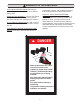
WARNINGS FOR THE HOMEOWNER 8 FOLLOW ALL INSTRUCTIONS and7 warnings printed in this manual and posted on the indirect water heater. D 6 5 protect walls, carpets, and valuables from water that could leak from the indirect water heater. PROTECT YOUR HOME IN FREEZING MAINTAIN THIS PRODUCT. To keep your indirect WEATHER.
CONTENTS I. Product Description . . . . . . . . . . . . . . . . . . . . . . . . . . . . . . . . . . . 5 II. Specifications . . . . . . . . . . . . . . . . . . . . . . . . . . . . . . . . . . . . . . . . 5 III. Before Starting Installation. . . . . . . . . . . . . . . . . . . . . . . . . . . . . . 7 IV. Locating The Indirect Water Heater . . . . . . . . . . . . . . . . . . . . . . 7 V. Piping . . . . . . . . . . . . . . . .. . . . . . . . . . . . . . . . . . . . . . . . . . . . . 8 A.
I. PRODUCT DESCRIPTION This indirect water heater (IWH) is designed to generate domestic hot water in conjunction with a hot water boiler, or other suitable heat source, using forced boiler water circulation. This indirect water heater consists of a stainless steel tank in which a smooth stainless steel coil is located. Boiler water is pumped through the coil and heats the water in the tank. This product is not intended for use in pool heating applications or for heating any other fluid other than water.
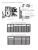
FIGURE 2.2: MEGA-STOR II INDIRECT WATER HEATER 30-3/4 LIFTING LUG T & P VALVE HOT WATER OUT TO BOILER SUPPLY A E THERMOSTAT D TO BOILER RETURN COLD WATER IN C DRAIN B MS2-030 THRU MS2-075 MS2-119 TABLE 2.3: PHYSICAL SPECIFICATIONS Model MS2-030 MS2-040 MS2-050 MS2-075 MS2-119 Potable Volume (Gal.) 30.1 37.9 50.6 74.0 111.
III. BEFORE STARTING INSTALLATION 1) Be sure that the planned installation is in accordance with all local codes. 2) Be certain the domestic water supply to the indirect water heater (IWH) has physical and chemical characteristics that fall within the limits shown below. Where questions exist as to the composition of the water on the job, a qualified water treatment expert should be consulted. 3) Read and understand all installation requirements in this manual.
V. PIPING A) BOILER SIDE PIPING CAUTION 1. The heat transfer-medium must be water or other nontoxic fluid having a toxicity rating or Class of 1, as listed in Clinical Toxicology of Commercial Products, 5th edition. 2. The pressure of the heat transfer medium must be limited to a maximum of 30 PSIG by an approved safety or relief valve. NOTICE Use of the minimum pipe sizes shown in Table 7.2 is strongly recommended.
The maximum equivalent length shown in Table 5.2 is that for the indirect water heater loop (IWH loop). The IWH loop piping is shaded in Figure 5.1. To calculate the equivalent length of this loop: 1) Count all fittings in the planned boiler loop. 2) Using Table 5.3, find the equivalent length of each fittings in the IWH loop. In doing this, keep the following in mind: a. In many cases, there will be more than one pipe size in the IWH loop.
TABLE 5.3: EQUIVALENT LENGTHS FOR SELECT VALVES AND FITTINGS (MAY BE USED FOR COPPER OR THREADED FITTINGS) Nominal Pipe Size 1” 1-1/4” 2.8 3.8 1.4 1.9 5.5 8.0 1.8 2.5 0.7 0.8 0.7 0.8 7.0 10.0 Not Recommended 46.1 3.0 8.0 Fitting 90° Elbow 45° Elbow 90° Turn in Tee Run of Tee Gate Valve (Open) Full Port Ball Valve Swing Check Valve Zone Valve (3.5 Cv) Zone Valve (8.0 Cv) Air Scoop FIGURE 5.
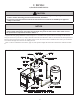
BASIC DOMESTIC PIPING B) DOMESTIC SIDE PIPING Figure 5.6 shows typical domestic water piping. All components except the control are provided by the installer. The function of the components shown are as follows: a) Temperature Control (required) - This control is provided by the factory and must be installed in the control well location shown in Figure 2.2. Remove the cover and loosen the clamping screw. Apply the silver heat conductive compound supplied to bulb.
FIGURE 5.5: AQUASTAT INSTALLATION T&P valve discharge to the outdoors or to other locations where water in this pipe could freeze or become blocked by debris. Make sure all discharge piping is pitched so as to allow complete drainage of any water in the line. h) Heat Trap (Optional) - The heat trap retards the migration of heat from the IWH up the hot water supply pipe. i) Vacuum Breaker (Recommended) - This valve protects the IWH in the event that the pressure in the tank falls below atmospheric.
FIGURE 5.6: BASIC DOMESTIC WATER PIPING WARNING If IWH is replacing a tankless coil, drain tankless coil and leave open to atmosphere. Do not plug coil. TABLE 5.7: MINIMUM T&P VALVE CAPACITY REQUIREMENTS (BTU/hr) Model MS2-030 MS2-040 MS2-050 MS2-075 MS2-119 Max Boiler Water Limit Setting 220°F or Less 221° - 250°F 100,000 112,300 100,000 133,700 100,000 156,300 115,000 195,600 199,900 Note 1 1.
FIGURE 5.8: DOMESTIC HOT WATER PIPING USING A MIXING VALVE WARNING If anti-scald or anti-chill protection is required, use devices specifically designed for such service. Install in accordance with their manufacturer’s instructions. CAUTION Do not attempt to use the anode rod tapping to make field connections of any type. Attempts to do so may result in unreliable operation or premature tank failure.
VI. WIRING The following general notes apply to all wiring: 1) Wiring must be done in accordance with all codes. In the absence of any codes the system must be wired in accordance with the National Electric Code (ANSI/NFPA 70). 2) The indirect water heater (IWH) is equipped with Honeywell a L4080B series temperature control. This control has a set of contacts which make upon a call for domestic water and break when this temperature is satisfied. A. BASIC CIRCULATOR ZONE WIRING Figure 6.
B. ZONE VALVES Figure 6.2 is a connections diagram for a zone system using Honeywell V8043F motorized zone valves. The motor on these valves is connected between TH and TR. TH/TR is provided for the electrician’s convenience as a binding post and is connected to nothing inside the valve. The “end switch” terminals are connected to a set of switch contacts inside the valve which become made when the valve is open.
VII. START-UP AND CHECK-OUT 1) Make sure that the system is free of leaks and that air is purged from the system. DANGER Never attempt to fill a hot empty boiler WARNING Fix any leaks found before proceeding further. Leakage from the boiler piping can result in severe damage to the boiler. 2) Many soldering fluxes contain zinc chloride which can cause severe corrosion damage to stainless steel.
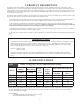
APPROXIMATE TIME/TEMPERATURE RELATIONSHIPS FOR SCALDING 120°F 125°F 130°F 135°F 140°F 145°F 150°F 155°F More than 5 minutes 1-1/2 to 2 minutes About 30 seconds About 10 seconds Less than 5 seconds Less than 3 seconds About 1-1/2 seconds About 1 second TABLE 7.2: SCALD RISK FIGURE 7.1: TEMPERATURE CONTROL VIII. MAINTENANCE This indirect water heater (IWH) is an extremely simple device and as such requires very little maintenance.
* The IWH depends upon the boiler for a source of heat and is therefore only as reliable as the boiler. Make sure that the boiler is maintained in accordance with the boiler manufacturer’s instructions. * If a water treatment system is required to keep the water chemistry within the parameters shown in page 7, make sure that this system is properly maintained. IX. PARTS MEGA-STOR II Key # 1 2 Part # 3503405 350085 3 220400 Description Thermostat (L4080B1352) Heat conductive grease, 1/2 oz.
APPENDIX A. SIZING NOTICE The following procedures are used to size indirect water heaters based on the amount of hot water which will be required during a given hour. In doing so it is assumed that this demand will be evenly spread out over the course of the entire hour. THESE SIZING PROCEDURES ARE PROVIDED AS A GUIDE TO ASSIST THE PROFESSIONAL INSTALLER IN SIZING INDIRECT WATER HEATERS.
Table 3.2: Maximum Possible Continuous Draw (180F Boiler Supply, 77F DHW Rise, 135F Outlet) (a) (b) (c) Continuous Draw Min Boiler Output Model (Gal/min) (MBH) MS2-030 2.3 87 MS2-040 2.7 101 MS2-050 3.2 121 MS2-075 3.9 150 MS2-119 6.9 264 Table 3.3: AHRI First Draw Rating* (a) (b) (c) Model Draw Rate (GPM) First Draw Rating (Gal) MS2-030 MS2-040 MS2-050 MS2-075 MS2-119 2.3 2.7 3.2 3.9 6.
CONSUMER WARRANTY INFORMATION MEGA‐STOR2: STAINLESS STEEL INDIRECT WATER HEATER By this warranty statement Velocity Boiler Works, LLC of Philadelphia, Pennsylvania issues a limited warranty subject to the terms and conditions stated below. This limited warranty applies to the stainless steel indirect‐fired water heater series labeled MEGA‐STOR2.