D E S I G N E D T O L E A D MAXI-THERM Glass Lined Indirect Water Heater INSTALLATION AND OPERATING INSTRUCTIONS Models: • MT040G • MT050G • MT079G • MT100G WARNING: Improper installation, adjustment, alteration, service or maintenance can cause property damage, injury, or loss of life. For assistance or additional information, consult a qualified installer or service agency. Read these instructions carefully before installing or using. Manufacturer of Hydronic Heating Products P.O.
CONTENTS I. II. III. Product Description......................................................................... 2 Specifications...................................................................................2 Designing A Maxi-Therm System......................................................4 “Quick” Residential..........................................................................5 Detailed Residential..........................................................................6 Commercial..........
I. PRODUCT DESCRIPTION The Crown MT series indirect water heater is designed to generate domestic hot water in conjunction with a hot water boiler using forced boiler water circulation. This indirect water heater consists of an enameled steel tank in which a smooth coil is located. Boiler water is pumped through the coil and heats the water in the tank. The Maxi-Therm is not intended for use in heating any fluid other than water. It is also not intended for use in gravity hot water heating systems.
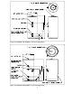
Figure 1a: MT040G and MT050G - General Configuration Figure 1b: MT079G and MT100G - General Configuration 3
III. DESIGNING A MAXI-THERM SYSTEM IMPORTANT The following procedures are used to size indirect water heaters based on the amount of hot water that will be required during a given hour. In doing so it is assumed that this demand will be evenly spread out over the course of the entire hour. THESE SIZING PROCEDURES ARE PROVIDED AS A GUIDE TO ASSIST THE PROFESSIONAL CONTRACTOR IN SIZING MAXI-THERMS.
METHOD A: “QUICK” RESIDENTIAL Table 2 shows some typical applications into which many “residential” applications can be classified. This procedure will provide satisfactory results most of the time. Where greater accuracy is desired, use Method B. 1) Find the description that best fits the installation and select the Maxi-Therm called for. Also note the required boiler output under column (f).
METHOD B: “DETAILED” RESIDENTIAL 1) Record the total number of each type of fixture in column (c) of Worksheet 1. If a whirlpool (Jacuzzi) is installed, record all fixtures EXCEPT the whirlpool faucet. 2) For each line multiply the quantity entered in column (c ) by the corresponding hourly usage in column (b). Enter the result in column (d). 3) Total column (d). This is the PEAK HOUR DEMAND. 4) Multiply the Peak Hour Demand by 1.20. This is the ADJUSTED PEAK HOUR DEMAND.
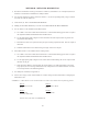
WORKSHEET 1: SINGLE FAMILY RESIDENCE (a) (b) 135F WATER PER FIXTURE (Gal/hr) FIXTURE DESCRIPTION Shower: (3 GPM Head) (5 GPM Head) (7 GPM Head) Bath (30 Gal. Tub) Vanity Clothes Washer Dishwasher Kitchen Sink or Utility Tub (c) TOTAL NUMBER OF FIXTURES (d) 135F WATER PER TYPE OF FIXTURE (Gal/hr) 21.0 35.0 49.0 21.0 2.8 48.0 15.0 X X X X X X X = = = = = = = 10.0 X = Peak Hour Demand = Total Column (d) Peak Hour Demand X 1.
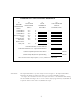
Figure 2: Completed Worksheet 1 and Boiler Output Graph From Example 1 WORKSHEET 1: SINGLE FAMILY RESIDENCE (a) (b) 135F WATER PER FIXTURE (Gal/hr) FIXTURE DESCRIPTION Shower: (3 GPM Head) (5 GPM Head) (7 GPM Head) Bath (30 Gal. Tub) Vanity Clothes Washer Dishwasher Kitchen Sink or Utility Tub (c) TOTAL NUMBER OF FIXTURES 21.0 35.0 49.0 21.0 2.8 48.0 15.0 X X X X X X X 10.0 X (d) 135F WATER PER TYPE OF FIXTURE (Gal/hr) 2 1 1 = = = = = = = 1 = 10.0 = = 162.6 195.
METHOD C: COMMERCIAL 1) Table 3 shows demands for various fixtures found in commercial buildings in gallons per hour. To determine the hot requirements of the building: a) Using Worksheet 2, determine and record the total number of each type of fixture in the building under column (2). b) Use Table 3 to find the number of gallons of 135F water used per hour. Record this value per fixture in column (1). Hourly usage of some commercial kitchen fixtures is shown in Worksheet 2.
3) Several Maxi-Therms may be used together if needed. If this must be done keep the following in mind: • • • • • The first hour rating of several Maxi-Therms may be added together to give a first hour rating for the total system. The boiler outputs for the individual Maxi-Therms must be totaled to provide the boiler output required for the system. The boiler water flow rate on which each individual Maxi-Therm’s First Hour Rating is based must be developed through the coil of each tank.
WORKSHEET 2: COMMERCIAL SIZING (1) 135F WATER PER FIXTURE (Gal/hr) Fixture Description: Basins, Private Lavatory Basins, Public Lavatory Bathtubs Showers Circular Wash Sinks Semi Circular Wash Sinks Foot Basins Laundry, Stationary Tubs Kitchen Sink Dishwasher in Apartment Clothes Washer in Apartment Commercial Kitchen Fixtures: Vegetable Sink Single Pot Sink Double Pot Sink Triple Pot Sink Bar Sink (2) (3) 135F WATER PER TYPE OF FIXTURE (Gal/hr) TOTAL NUMBER OF FIXTURES 15 48 X X X X X X X X X X X =
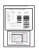
Figure 3: Use of Worksheet 2 and Boiler Output Graphs From Example 2 WORKSHEET 2: COMMERCIAL SIZING Fixture Description: (1) 135F WATER PER FIXTURE (Gal/hr) (2) (3) 135F WATER PER TYPE OF FIXTURE (Gal/hr) TOTAL NUMBER OF FIXTURES Basins, Private Lavatory Basins, Public Lavatory Bathtubs Showers Circular Wash Sinks Semi Circular Wash Sinks Foot Basins Laundry, Stationary Tubs Kitchen Sink Dishwasher in Apartment Clothes Washer in Apartment 15 48 X X X X X X X X X X X Commercial Kitchen Fixtures: Veg
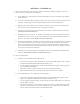
FIRST HOUR RATING (GAL/hr) 250 200 150 100 50 0 0 50000 100000 150000 BOILER OUTPUT (BTU/hr) FIRST HOUR RATING (GAL/hr) Figure 4b: MT050G Ratings at Different Boiler Outputs 350 300 250 200 150 100 50 0 0 50000 100000 150000 BOILER OUTPUT (BTU/hr) Figure 4c: MT079G Ratings at Different Boiler Outputs 13 200000
FIRST HOUR RATING (GAL/hr) 450 400 350 300 250 200 150 100 50 0 0 50000 100000 150000 200000 250000 BOILER OUTPUT (BTU/hr) Figure 4d: MT100G Ratings at Different Boiler Outputs Table 4: 135F Water Available at Various Flow Rates Starting with a Fully Recovered Maxi-Therm Model MT040G Time (min.) Gallons. MT050G Time (min.) Gallons. MT079G Time (min.) Gallons. MT100G Time (min.) Gallons. Boiler Output (BTU/hr) 3.0 5.0 Draw Rate (GPM) 7.5 9.0 11.9 35.6 6.8 33.9 4.2 31.2 3.2 29.2 103149 Ind.
Zone Design In designing the Maxi-Therm zone piping system the following points should be considered: 1) Circulator or Zone Valve Zoning? – Circulator zones are usually a better choice. Zone valves have a relatively high pressure drop at the flow rate required through the Maxi-Therm (see Table 1). 2) If zone valves are selected, use a zone valve with a minimal delay in opening, such as a motorized type.
WORKSHEET #3: Pressure Drop Calculations Through Maxi-Therm Zone (1) Fitting Description MT040G Coil MT050G Coil MT079G Coil MT100G Coil 1 ft 1" St. Pipe 1 ft 1-1/4" St. Pipe 1 ft 1-1/2" St. Pipe 1" 90 El 1-1/4" 90 El 1-1/2" 90 El 1" Run of Tee 1-1/4" Run of Tee 1-1/2" Run of Tee 1" Branch in Tee 1-1/4" Branch in Tee 1-1/2" Branch in Tee 1" Std. Ball Valve 1-1/4" Std. Ball Valve 1-1/2" Std.
Table 5: Selecting a Circulator Available Head (ft w.c.) 8.0 Gal/min 10.0 Gal/min 8.2 7.3 9.8 7.2 22.8 21.0 11.0 9.0 21.0 19.5 23.0 21.0 Circulator Taco007 Taco 008 Taco 0011 Grundfos UPS 15-42F Grundfos UPS 26-64F Grundfos UPS 26-96F Figure 4: Example of Use of Worksheet 3 WORKSHEET #3: Pressure Drop Calculations Through M axi-Therm Zone [a] Fitting Des cription MT040G Coil MT050G Coil MT079G Coil MT100G Coil 1 ft 1" St. Pipe 1 ft 1-1/4" St. Pipe 1 ft 1-1/2" St.
IV. BEFORE STARTING INSTALLATION 1) Be sure that the planned installation is in accordance with all local codes. Also note that some jurisdictions may not permit the installation of an MT079G or MT100G with a boiler having a gross output in excess of 200,000 BTU/hr. Consult the authority having jurisdiction before installing a MT079G or MT100G with a boiler having an output in excess of 200,000 BTU/hr. 2) Read and understand all installation requirements in this manual. V.
3) The Maxi-Therm may be located some distance from the boiler provided the zone system is designed to provide the flow called for in Table 1 through the coil. Also, the further the Maxi-Therm is from the boiler, the longer the response of the boiler will be to a call from the Maxi-Therm zone. If long runs exist between the boiler and Maxi-Therm, it is advisable to insulate the piping.
VI. PIPING CAUTION Do not connect a Maxi-Therm to a boiler system having a significant amount of make up water or radiant tubing without an oxygen barrier. Doing so may cause premature failure of the Maxi-Therm coil. WARNING Install a relief valve on the boiler per the boiler manufacturer’s instructions. Also refer to the boiler manufacturer’s instructions and the authority having jurisdiction for other possible boiler-side piping requirements, such as low water cut-offs or flow switches.
Figure 6: Boiler-Side Piping Using Circulator Zones Figure 7: Boiler-Side Piping Using Zone Valves (2-Way) 21
RADIANT PANEL OR OTHER “LOW TEMPERATURE” SYSTEM The First Hour Ratings published in this manual are based on a boiler supply temperature of 180F. If, for any reason, the boiler water temperature going to the heating system is held to levels under 180F, special piping is needed to provide boiler water to both the Maxi-Therm and the heating system at the proper temperatures. Two ways of doing this are with a heat exchanger or a 4-way valve.
Figure 9: Boiler-Side Piping in a Low Temperature System Using a Heat Exchanger Figure 10: Boiler-Side Piping in a Low Temperature System Using a Mixing Valve 23
Figure 11: Boiler-Side Piping for Multiple Maxi-Therms DOMESTIC SIDE PIPING BASIC DOMESTIC PIPING Figure 12 shows typical domestic water piping for a Maxi-Therm. All components except the thermostat are provided by the installer. The function of the components shown are as follows: a) Thermostat (required) - This control is provided by Crown and must be installed in the location indicated. It is imperative that the bulb of the thermostat is “bottomed out” in the control well.
e) Dielectric Unions (recommended)- Used to electrically isolate the Maxi-Therm from the connected domestic water piping. This helps to minimize the possibility of corrosion damage to the Maxi-Therm. On the 40 and 50 gallon sizes, the hot water outlet is located in the clean out cover along with the anode rod. The union in the hot water connection simplifies inspection of the anode rod. f) Drain (required)- Used to drain the tank for inspection or servicing.
MAXI-THERM PIPING WITH A“MIXING VALVE” Usually, the maximum temperature of the outlet water will stay near the setting of the Maxi-Therm thermostat. In some cases, however, hot water usage patterns can cause the outlet water temperature to rise significantly above the control setting. The temperature of water going to the fixtures may be more carefully controlled through the use of a mixing valve.
Figure 12: Basic Domestic-Side Piping Figure 13: Domestic-Side Piping Using a Mixing Valve 27
Insulate dashed piping Figure 14a: Domestic-Side Piping Using a Recirculation Line (MT040G, MT050G) Insulate dashed piping Figure 14b: Domestic-Side Piping Using a Recirculation Line (MT079G, MT100G) 28
Figure 15: Domestic-Side Piping for Multiple Maxi-Therms 29
The following general notes apply to all wiring: 1) Wiring must be done in accordance with all codes. In the absence of any codes, the system must be wired in accordance with the National Electric Code (ANSI/NFPA 70-latest edition). 2) The control system for the boiler, Maxi-Therm, and heating zones must be on a dedicated circuit. The current rating of this circuit will depend on the total number and size of loads in the system, however it should in no case be less than 15 AMPS.
Figure 16: Non-Priority Circulator Zoning Using Honeywell R845a’s Figure 17: Priority Circulator Zoning 31
ZONE VALVES (2-WAY PRIORITY) Figure 19 is a connections diagram for a priority zone system using Honeywell V8043F motorized valves. An R8285B relay is used which is equipped with its own transformer and a set of SPDT contacts. The Maxi-Therm control is connected to terminal R and G on the R8285B so that when the Maxi-Therm control calls for heat, the relay coil is energized. One side of the transformer is connected to the common contact.
Figure 19: Zone Valve Wiring (2-Way, Priority) Note: Connect Zone Valve Port “A” to Maxi-Therm, Port “B” to Heating Zone, “AB” to boiler return Figure 20: Zone Valve Wiring (3-Way, Priority Using Honeywell V8044E1101 ) 33
VIII. START-UP 1) Make sure that the system is free of leaks and that air is purged from the system. 2) After completing all domestic water connections, flush the domestic side of the Maxi-Therm thoroughly before leaving the installation. Flushing the domestic water side of the Maxi-Therm will minimize the presence of WARNING Never attempt to fill a hot empty boiler. IMPORTANT Fix any leaks found before proceeding further.
IX. MAINTENANCE The Maxi-Therm is an extremely simple device and as such requires very little maintenance. There are, however, several items that should be checked out on an annual or as needed basis to ensure a reliable supply of hot water: 1) On an annual basis, remove the jacket cover over the hand hole and make sure that the hand hole gasket is leak-tight.
X. OPERATING INSTRUCTIONS WARNING There are no user serviceable parts on this product. Attempts to service this product by someone other than a licensed plumber or heating technician could void the warranty, cause property damage, personal injury or loss of life. DANGER • Water temperature over 125°F can cause severe burns instantly or death from scalds. • Children, disabled and elderly are at highest risk of being scalded. • Set the Maxi-Therm thermostat as low as practical.
XI. PARTS The following parts may be obtained from any Crown distributor. To find the closest Crown distributor consult the area Crown representative or the factory: Crown Boiler Co. 3633 I St. Philadelphia Pa.
Parts - MT079G, MT100G KEY # 1 2 3 4 5 6 6 7 7 8 9 10 11 12 PART DESCRIPTION THERMOSTAT (L4006A2114) 3/4 SHORT WELL CLEAN OUT COVER CLEAN OUT GASKET M12 x 30mm CAP SCREW ANODE ROD (MT079G) ANODE ROD (MT100G) JACKET WRAPPER (MT079G) JACKET WRAPPER (MT100G) TOP INSULATION JACKET CAP CLEAN OUT INSULATION CLEAN OUT CAP #10 x 1/2 SHEET METAL SCREW 38 CROWN P.N. 35-3200 35-1010 220005 220006 900020 220011 220012 220079 220100 220070 220075 220080 220081 90-212 QTY.
APPENDIX A: WHIRLPOOL SIZING 1) If not already done, use one of the procedures in Part III to size a Maxi-Therm/boiler combination for all fixtures EXCEPT the whirlpool tub. 2) Find the nominal volume of the whirlpool tub. This should be listed on the tub manufacturer’s literature. 3) If the whirlpool tub has a volume greater than the Maxi-Therm(s) selected in (1), increase the size of the Maxi-Therm selected to one with a volume greater than or equal to the volume of the tub.
Manufacturer of Hydronic Heating Products P.O. Box 14818 3633 I. Street Philadelphia, PA 19134 Tel: (215) 535-8900 • Fax: (215) 535-9736 • www.crownboiler.