Commercial Audio Series 180A B T B T B T 1160A Operation Manual 280A B T 660A Obtaining Other Language Versions: To obtain information in another language about the use of this product, please contact your local Crown Distributor. If you need assistance locating your local distributor, please contact Crown at 574-294-8000. This manual does not include all of the details of design, production, or variations of the equipment.
Commercial Audio Series Amplifiers Important Safety Instructions MAGNETIC FIELD 1) 2) 3) 4) 5) 6) 7) 8) 9) 10) 11) 12) 13) 14) page 2 Read these instructions. Keep these instructions. Heed all warnings. Follow all instructions. Do not use this apparatus near water. Clean only with a dry cloth. Do not block any ventilation openings. Install in accordance with the manufacturer’s instructions.
Commercial Audio Series Amplifiers DECLARATION of CONFORMITY Crown International, Inc. Issued By: Crown International, Inc. 1718 W. Mishawaka Road Elkhart, Indiana 46517 U.S.A. FOR COMPLIANCE QUESTIONS ONLY: Sue Whitfield 574-294-8289 swhitfield@crownintl.com European Representative’s Name and Address: Nick Owen 35, Bassets Field Thornhill Cardiff.
Commercial Audio Series Amplifiers Table of Contents Important Safety Instructions .......................................................2 3 Troubleshooting .................................................................. 14 Declaration of Conformity ............................................................3 4 Specifications ..................................................................... 15 1 Welcome ................................................................................
Commercial Audio Series Amplifiers 180A Minimum guaranteed power into 4 ohms or 70V/100V output *1 kHz Power 80W B T B T *1 kHz Power: refers to maximum power in watts at 1 kHz with 0.5% THD. 280A Minimum guaranteed power per channel into 4 ohms or 70V/100V output *1 kHz Power 80W *1 kHz Power: refers to maximum power in watts at 1 kHz with 0.5% THD. 1160A Minimum guaranteed power into 4 ohms or 70V/100V output *1 kHz Power 160W *1 kHz Power: refers to maximum power in watts at 1 kHz with 0.
Commercial Audio Series Amplifiers 1 Welcome 1.2 Front Panel Controls and Indicators (280A shown; other models are fairly similar) A. Master Volume Controls One per output channel. Detented potentiometer with knob. B. Output Signal Presence Indicator Green LED, one for each output channel, illuminates when output signal level exceeds 100 mV (45 dB below full power) from the 4-ohm tap. C. Clip Indicator Red LED, one per output channel, illuminates at threshold of audible distortion. D.
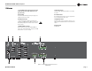
Commercial Audio Series Amplifiers 1 Welcome 1.3 280A Back Panel Controls and Connectors (180A and 1160A are fairly similar. See next page for 660A). J. Amp Input Connector 3-pin Phoenix-type, high-impedance balanced, one per amplifier channel. G. Reset Switch Resets the circuit breaker that protects the power supply. 220/ 230/240V units have a fuse instead. K. Line Out Connector One 3-pin balanced Phoenix-type connector per output channel. Level controlled by master volume control. H.
Commercial Audio Series Amplifiers 1 Welcome 1.4 660A Back Panel Controls and Connectors A. Reset Switch Resets the circuit breaker that protects the power supply. 220/ 230/240V units have a fuse instead. B. Amplifier Outputs Connector One 4-position terminal strip for channels 5 and 6 including COM and 4-ohms terminals for each channel. Accepts up to 10 AWG terminal forks. D. Amp Input Connector 3-pin Phoenix-type, high-impedance balanced, one per amplifier channel. E. AC Power Inlet Detachable IEC. F.
Commercial Audio Series Amplifiers 2 Setup 2.1 Installation 2.2 How to Attach Rack Ears CAUTION: Before you begin, make sure your amplifier is disconnected from the power source, with the power switch in the “off” position and all level controls turned completely down (counterclockwise). 1. Locate the two rack ears and two rack-ear screws supplied. 2. See Figure 2.2. Remove the two screws from each side of the chassis near the front. 3. Place a rack ear flush with the right front of the chassis. 4.
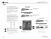
Commercial Audio Series Amplifiers 2 Setup 2.3 Choose Input Wire and Connectors Crown recommends using pre-built or professionally wired balanced line (two-conductor plus shield), 22-24 gauge cables and connectors. You should use 3-pin Phoenix-type cable ends at the amplifier inputs. Unbalanced line may also be used but may result in noise over long cable runs. Figure 2.3 shows connector pin assignments for balanced wiring, and Figure 2.4 shows connector pin assignments for unbalanced wiring.
Commercial Audio Series Amplifiers 2 Setup 2.5 Wire Your System Typical input and output wiring for the 180A, 280A and 1160A is shown in Figure 2.7. See Figure 2.8 for 660A wiring. INPUTS: Connect balanced line-level sources to amplifier balanced inputs. OUTPUTS: Maintain proper polarity (+/–) on output connectors. Ceiling Speakers For each amplifier channel, connect the Amplifier Output screw terminals to the loudspeaker loads.
Commercial Audio Series Amplifiers 2 Setup 4 ohms 4 ohms Figure 2.
Commercial Audio Series Amplifiers 2 Setup 2.6 Remote Volume Control 2.7 Powering Up You can control the volume of each amplifier channel remotely. To do so, locate the OUTPUT VCA connector on the back panel. Insert a 4-pin Phoenix-type cable connector into the OUTPUT VCA connector. Wire a Crown 1-VCAP or 4-VCAP level control to the Phoenix-type cable connector terminals as shown in Figure 2.11. 1. Turn off any equipment connected to the Line Out connectors. 2.
Commercial Audio Series Amplifiers 3 Troubleshooting CONDITION: No power to the amplifier. POSSIBLE REASON: • The amplifier’s Power switch is off. • The amplifier is not plugged into the power receptacle. • The amplifier’s high-voltage power supply circuit breaker has tripped, or the fuse has opened on 220/230/240V models. Verify that the AC mains voltage is correct, then press the Reset button on the back panel. • If the unit is operated from a 24V DC supply, the internal fuse may have opened.
Commercial Audio Series Amplifiers 4 Specifications Minimum Guaranteed Power 180A 280A 1160A 660A 120 VAC, 60 Hz Units, per channel, all channels driven 1 kHz with 0.
Commercial Audio Series Amplifiers 5 Service Crown amplifiers are quality units that rarely require servicing. Before returning your unit for servicing, please contact Crown Technical Support to verify the need for servicing. ber to transport the unit in the original factory pack. A list of authorized service centers in your area can be obtained from Crown Factory Service, or online from http://www.crownaudio.com/support/servcent.htm.
Commercial Audio Series Amplifiers 6 Warranty UNITED STATES & CANADA SUMMARY OF WARRANTY Crown International, 1718 West Mishawaka Road, Elkhart, Indiana 46517-4095 U.S.A. warrants to you, the ORIGINAL PURCHASER and ANY SUBSEQUENT OWNER of each NEW Crown product, for a period of three (3) years from the date of purchase by the original purchaser (the “warranty period”) that the new Crown product is free of defects in materials and workmanship.
Commercial Audio Series Amplifiers 6 Warranty (continued) WORLDWIDE EXCEPT USA & CANADA SUMMARY OF WARRANTY WHAT THE WARRANTOR WILL DO Crown International, 1718 West Mishawaka Road, Elkhart, Indiana 46517-4095 U.S.A.
Commercial Audio Series Amplifiers PRODUCT REGISTRATION Crown International 1718 W. Mishawaka Rd. Elkhart, IN 46517-9439 Phone: 574-294-8000 Fax: 574-294-8329 www.crownaudio.com Online registration is also available at http://crownweb.crownintl.com/webregistration. Warranty is only valid within the country in which the product is purchased. When this form is used to register your product, it may be mailed or faxed.
Commercial Audio Series Amplifiers THIS PAGE INTENTIONALLY LEFT BLANK page 20 Operation Manual
Commercial Audio Series Amplifiers Crown Audio Factory Service Information Shipping Addressrown Audio Factory Service, 1718 W. Mishawaka Rd., Elkhart, IN 46517 PLEASE PRINT CLEARLY SRA #: __________________(If sending product to Crown factory service.
Commercial Audio Series Amplifiers THIS PAGE INTENTIONALLY LEFT BLANK page 22 Operation Manual
Commercial Audio Series Amplifiers THIS PAGE INTENTIONALLY LEFT BLANK Operation Manual page 23