
Instruction manual


Operation Manual
CH and CL Series Power Amplifiers
page 18
The red Fault indicators blink under five dif-
ferent conditions:
1. When the amplifier is first powered up, until
the unit is ready for operation.
2. If the heatsinks reach a temperature above
normal working limits. This can be caused by
any number of abnormal conditions including
but not limited to extremely low load imped-
ance and/or inadequate cooling (see Section 1
for more information on cooling).
3. If the transformer (high-voltage power sup-
ply) thermal protection circuit is activated.
Higher than rated output levels, excessively
low-impedance loads and unreasonably high
input signals can generate more heat in the
power supply than in the output devices. This
can overheat the power supply and activate the
Fault protection circuit.
4. If amplifier output wires develop a short-cir-
cuit. This could be caused by a short anywhere
along the circuit from the output connectors to
the speakers, including shorted speaker driv-
ers.
5. If the amplifier output stage stops operating.
The red Clip indicators turn on when distor-
tion is audible in the amplifier output.
The green Signal Presence Indicators
(SPI) illuminate when a signal (>–40 dBm) is
present at the INPUT of the amplifier. This indi-
cator is before the level control, so it can be
used to troubleshoot wiring problems within a
system. If the indicators are not lit, signal is not
reaching the amplifier.
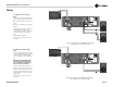
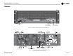
3.3 Controls
The Enable switch is located on the front
panel so you can easily turn the amplifier on
and off.
A 21-position Detented Level Control is
provided for each channel. Level attenuation
may be adjusted in steps. For security, the level
controls are located on the back panel.
A two-position Mode switch, located on the
back panel, allows the selection of either Stereo
or Bridge mode of operation.
Stereo mode provides identical power output to
each of the two amplifier output channels.
Bridge mode combines the two amplifier output
channels into a single mono channel with twice
the voltage of a single stereo channel. It does
this by bridging the outputs, and it requires
special output wiring. Do NOT select Bridge
mode without first making sure the
amplifier has been wired in a Bridge-
Mono configuration. For more information
on wiring for Bridge mode, see the Setup sec-
tion of this manual (Section 2), or consult your
system installer.
When Bridge mode is selected, only the Chan-
nel 1 Level control and the Channel 1 Signal
indicator will work. If the Channel 2 input is
wired, the Channel 2 Level Control should be
turned all the way down (counter/anti-clock-
wise) to prevent distortion.
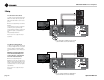
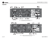
A two-position Output Operation switch
(CH Series amplifiers only) allows the selection
of either 4/8 ohm or 70V output from the ampli-
fier. See Section 2 for more information about
output operating modes.
Fault Jack: This RJ11 jack (which looks like a
phone jack) is located on the back panel. By
attaching a signalling device to the Fault jack,
you can monitor the amplifier’s Fault status
from a remote location. See Section 4.3.3 for
more information on fault monitoring and sug-
gestions for signalling device circuity.
A circuit breaker is provided to prevent the
high-voltage power supplies from drawing
excessive current. A Reset switch for the cir-
cuit breaker is provided on the back panel. If
the circuit breaker trips, the Power indicator
turns off. In this situation, turn off the Power
switch and reset the circuit breaker. Then, turn
the Power switch back on. If it trips again or the
unit fails to operate properly, contact an autho-
rized Crown Service Center or Crown Factory
Service.
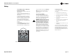
3 Operation
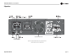
3.2 Indicators
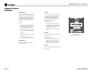
The front panel of a Contractor Series amplifier
has several helpful indicators (Figure 3.6). The
blue Power indicator shows that the amplifier
has been turned on and has power.
Figure 3.6 Indicators
SIGNAL SIGNAL
CLIP CLIP
FAULT FAULT
POWER