
Instruction manual

page 27
CH and CL Series Power Amplifiers
Operation Manual
normally runs at very low speed when the
amplifier is idling or when it is being used for
low to moderate duty work. If the amplifier is
delivering large amounts of power into low
impedance loads, the heatsinks or transformer
may heat up enough to increase the speed of
the fan to medium and possibly to high speed.
If the temperature continues to increase, the
TLC circuit uses the compressor to reduce the
gain of the input stage and thus reduce the
power dissipated by the amplifier. As a further
protective measure, if the temperature contin-
ues to rise (due to blocked airflow for example),
the amplifier will stop running and keep the fan
on high speed to quickly bring the temperature
back to an operational level.
If a signal presented at the input of the amplifier
will not be passed through to the output, the
Fault LED will blink to get your attention. The
turn-on delay, for example, will cause each
channel’s LED to blink because the amplifier
remains in standby for a few seconds before it
allows audio output.
An RJ11 modular jack is mounted on the back
panel. Pins 2 and 5 are connected to an opto-
isolator that is always in a low-resistance state
whenever the unit is on and happy. Should a
fault be detected or should the amplifier lose
AC power, the opto-isolator will change to a
high resistance, allowing the user to remotely
detect the status of the amplifier.
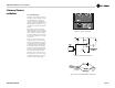
The Signal Presence Indicators tap the signal
chain just before the level controls and prior to
the power amplifier chain. They are not ampli-
fier output indicators and should only be used
to indicate the presence of signal to the ampli-
fier front end.
The Clip indicators are driven from the output
of the compressor circuitry and light to indicate
the onset of audible distortion. The Power indi-
cator LED is driven from the low-voltage sup-
ply.
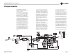
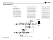
5.2.2 Power Supply Operation
AC power enters the amplifier through a power
cord equipped with an IEC (unplugable) con-
nector. It then is passed through the EMI filter.
Circuits that use switching technology will nor-
mally send a small amount of high-frequency
noise back down the power cord and into the
power distribution system. This noise must be
removed in order to sell the unit in certain parts
of the world. Since the CH4/CL4 is a worldwide
product, the EMI filter removes this noise so
that it does not exit the box.
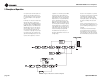
The power then enters the Power Factor Cor-
rection (PFC) Boost stage. This stage is what
allows the CH4/CL4 to be plugged into any
outlet in the world without any modifications to
the amplifier. The PFC stage uses switching
power supply technology to take whatever AC
line voltage comes in, convert it to DC and
boost it to 400 Volts. The circuit also uses
intelligence to draw the current from the line
sinusoidally and in phase with the line voltage.
This reduces the load on the power companies
and also allows the amplifier to pull more peak
power from the power source (the outlet). The
power is drawn in small amounts 62,500 times
each second and is used to provide power to
the isolation stage and to fill the large energy
reservoir capacitors.
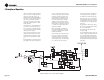
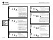
The power then goes to the “buck” isolation
stage. This stage takes the 400 Volt PFC volt-
age and, again using switching power supply
technology, converts it down (“bucks” it down)
to the level needed to power the audio output
stage. The isolation stage also satisfies a safety
requirement by providing isolation, using a
transformer, between the AC mains power and
the power that is delivered to the speakers. The
isolation stage moves power 125,000 times
each second from the primary to the secondary
to power the audio output stage and keep its
large energy reservoir capacitors full.
In order to keep the power supply controllers,
protection circuits, and the audio signal path
components powered, another switching power
supply is used, this one also running at 125
kHz. This one is also a “buck” type supply in
that it takes voltage from the 400 Volt PFC bus
and converts it down to the low voltages
needed. This circuit also uses a transformer to
provide safety isolation.
Like the audio signal path parts of the amplifier,
there are many ways that the power supply pro-
tects itself. Part of the start-up time delay men-
tioned above occurs while the power supply is
ramping up all of its voltages (soft-start) so that
large inrush currents are avoided. Current lim-
iters and over-current detectors are used to
protect the power supply output devices. The
power supply will also detect severe brownouts
and shut off the supply until the brown-out is
over if the line voltage is drastically less than
normal.
5 Principles of Operation