Com-Tech 400 Amplifier Service Manual POWER AMPLIFIER SERVICE MANUAL COM-TECH 400 ® Model CT400B ©1995 by CROWN INTERNATIONAL, INC. Mailing Address: P.O. Box 1000 Elkhart, IN U.S.A. 46515-1000 Shipping Address: 57620 C.R. 105 Elkhart, IN U.S.A. 46517 Com-Tech®, ODEP® and Crown® are registered trademarks of Crown International, Inc.
Com-Tech 400 Amplifier Service Manual The information furnished in this manual does not include all of the details of design, production, or variations of the equipment. Nor does it cover every possible situation which may arise during installation, operation or maintenance. If you need special assistance beyond the scope of this manual, please contact the Crown Technical Support Group. Mail: P.O. Box 1000 Elkhart IN 46515-1000 Shipping: 57620 C.R.
Com-Tech 400 Amplifier Service Manual Table of Contents Introduction ............................................................ 4 Parts Information .................................................... 5 Specifications ......................................................... 6 Theory .................................................................... 7 Electrical Checkout Procedures ........................... 12 Parts List (Non Module) .......................................
Com-Tech 400 Amplifier Service Manual Introduction This manual contains service information on Crown power amplifiers. It is designed to be used in conjunction with the applicable Owner's Manual. However, some important information is duplicated in this Service Manual in case the Owner's Manual is not readily available.
Com-Tech 400 Amplifier Service Manual Parts Information General Information Later sections include both mechanical and electrical parts lists for this product. The parts listed are current as of the date printed. Crown reserves the right to modify and improve its products for the benefit of its customers. Part Numbering System As of the printing of this manual, Crown is using two numbering systems. The elder system always uses eight characters. The first character is a letter.
Com-Tech 400 Amplifier Service Manual Specifications Unless noted otherwise, all specifications are based on driving an 8 ohm load per channel, both channels driven, the sensitivity switch in the 26dB position, the AC supply is 120VAC at 60Hz. Crown specifications are guaranteed through the warranty period (normally 3 years). Because our testing methods are more stringent than our published specifications, every Crown amplifier will exceed its published specifications.
Com-Tech 400 Amplifier Service Manual Theory Overview It should be noted that over time Crown makes improvements and changes to their products for various reasons. This manual is up to date as of the time of writing. For additional information regarding these amplifiers, refer to the applicable Technical Notes provided by Crown for this product. This section of the manual explains the general operation of a typical Crown power amplifier. Topics covered include Front End, Grounded Bridge, and ODEP.
Com-Tech 400 Amplifier Service Manual Theory Error Amp, called the Error Signal (ES) drives the Voltage Translators. Fault protective action. Last Voltage Amplifiers (LVAs) The Voltage Translator stage channels the signal to the Last Voltage Amplifiers (LVA's) in a balanced configuration. The +LVA and -LVA, with their push-pull effect through the Bias Servo, drive the fully complementary output stage. The LVAs are configured as common emitter amplifiers.
Com-Tech 400 Amplifier Service Manual Theory As the input drive voltage becomes more positive, the HS NPN conducts and delivers positive voltage to the load. Eventually the NPN devices reach full conduction and +Vcc is across the load. At this time the HS PNP is biased off. When the drive signal is negative going, the HS PNP conducts to deliver -Vcc to the load and the HS NPN stage is off. The output of the +LVA drives the base of predriver device.
Com-Tech 400 Amplifier Service Manual Theory inverted feedback from the HS output to control the ground reference for the rails (±Vcc). Both LS quadrants are arranged in a three-deep Darlington and are biased AB+B in the same manner as the HS. perform the same function as the HS flybacks. The output of the LS is tied directly to chassis ground via ground strap. When the amplifier output swings positive, the audio is fed to an op-amp stage where it is inverted.
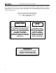
Com-Tech 400 Amplifier Service Manual Theory BGS BALANCED INPUTS VGS -1 POSITIVE HIGH SIDE OUTPUT NPN STAGE +LVA -1 +VOLTAGE TRANSLATOR ERROR AMP OUTPUT DEVICE EMULATION PROTECTION HIGH SIDE BIAS SERVO NEGATIVE HIGH SIDE OUTPUT PNP STAGE -LVA -1 -VOLTAGE TRANSLATOR MAIN NEGATIVE FEEDBACK (NFb) LOOP POSITIVE LOW SIDE OUTPUT NPN STAGE -1 INVERTING BRIDGE BALANCE LOW SIDE BIAS DIODE STRING NEGATIVE LOW SIDE OUTPUT PNP STAGE Figure 3.
Com-Tech 400 Amplifier Service Manual Electrical Checkout Procedures General Information The following test procedures are to be used to verify operation of this amplifier. DO NOT connect a load or inject a signal unless directed to do so by the procedure. These tests, though meant for verification and alignment of the amplifier, may also be very helpful in troubleshooting. For best results, tests should be performed in order. All tests assume that AC power is from a regulated 120 VAC source.
Com-Tech 400 Amplifier Service Manual Electrical Checkout Procedures Test 4: AC Power Draw Test 8: Level Controls Spec: 60 Watts maximum quiescent. Initial Conditions: Controls per standard. Procedure: With no input signal and no load, measure AC line wattage draw. If current draw is excessive, check for high AC line voltage or high bias voltage. Spec: Level controlled by level controls. Initial Conditions: Controls per standard. Procedure: No load. Inject a 1 kHz sine wave.
Com-Tech 400 Amplifier Service Manual Electrical Checkout Procedures Test 12: Output Power Spec at 8 Ohm Stereo: ≥ 215 Watts/Ch at 0.1% THD Spec at 4 Ohm Stereo: ≥ 230 Watts/Ch at 0.1% THD Spec at 70-V Mode, Stereo: ≥ 210 Watts/Ch at 0.1% THD Initial Conditions: Controls per standard Procedure: Load each channel to 8 ohms. Inject a 1 kHz sine wave and measure at least 41.47 VAC at the output of each channel. Load each channel to 4 ohms. Inject a 1 kHz sine wave and measure at least 30.
Com-Tech 400 Amplifier Service Manual Electrical Checkout Procedures Test 18: Intermodulation Distortion Spec at 0 dB output: ≤ 0.01%. Spec at -35 dB output: ≤ 0.05%. Initial Conditions: Controls per standard. Procedure: Load each channel to 8 ohms. Inject a SMPTE standard IM signal (60 Hz and 7 kHz sine wave mixed at 4:1 ratio). Set the 60 Hz portion of the sine wave to 32 volts RMS. Set the 7 kHz portion to 25%. With an IM analyzer measure less than 0.01% IMD.
Com-Tech 400 Amplifier Service Manual Parts List (Non-Module) Supplimental Items CPN A10087-71012 C 3342-0 D 4137-2 A10086-70808 A10101-12 F11489-6 K80636-2 Item Rack Screw, 10-32 x .75 Feet, Selfstick Black Nylon Washer Screw, 8-32 x .5 (For volume cover) Spacer, #8 x 5/16OD x 1/4L (For volume cover) Plexiglass Plate (Volume cover) CT Series Reference Manual Quantity 8 4 4 2 2 1 1 Item Screw, 10-32 x 1.
Com-Tech 400 Amplifier Service Manual Parts List (Non-Module) Back Panel Assembly CPN D 8367-1 A10086-10410 A10086-70808 A10094-2 A10100-7 A10109-70808 A10214-4 C10187-0 A11793-0105D A10793-0503D C 4508-5 C 5990-4 C 6821-0 C 7957-1 C 8812-7 C10060-9 D 6899-5 D 7623-8 F12690-8 P10286-6 Item Knob, .5 Dia. Level Control Screw, 4-40 x .62 Screw, 8-32 x .5 Lockwasher, #4 Internal Star Aluminum Spacer, .250OD x .140ID x .312L Screw, 8-18 x .
Com-Tech 400 Amplifier Service Manual Parts List (Non-Module) Main Chassis Assembly Cont. CPN C 6457-3 C 6912-7 C 6913-5 C 6914-3 C 7705-4 C 9491-9 C 9953-8 C10111-0 D 7060-3 F11632-1 F12642-9 Item Screw, #8 x 3/8 Tension Retaining Board Supports 1" Spacer Toggle Nut, Plastic .75" Spacer Toggle Nut, Plastic Flat Cable Clamp Screw, 6-32 x .312 Screw, 6-20 x .312 Button, Mtg. Sil Pad, 7 Mil 2.05 x .775 Bracket, Transformer Mtg. Chassis, 3.
Com-Tech 400 Amplifier Service Manual Module and Schematic Information Module History Control Module: The Com Tech 400B amplifier was introduced in 1990. Since then there have been several updates and revisions, some of which called for new modules. The following is a list of all modules used up to this date, December 1995. Q42762-7 CT-200/400 fan control on P10317-9 board. Q43214-8 CT-400/800 fan control on P10404-5 board. Q43242-9 CT control module for Export models. On P10405-2 board.
Com-Tech 400 Amplifier Service Manual Q42762-7 Control Module (P10317-9 board) Parts Lists Capacitors C700 C701 C900 C901 Resistors C800 C801 C 8426-6 C 8426-6 C 8963-8 C 8963-8 .1µF 250V .1µF 250V .47µF 250V .
Com-Tech 400 Amplifier Service Manual Q43214-8 Control Module (P10404-5 board) Parts List Capacitors C700 C701 C900 C901 Resistors C800 C801 C C C C 8426-6 8426-6 8963-8 8963-8 D800 C 3181-2 C 2851-1 .1µF 200V .1µF 200V .47µF 250V .47µF 250V Diodes D700 D900 1N4148 1N4004 R800 R801 A10266-1222 A10266-1812 A10266-2722 A10266-1021 C 7669-2 C 7669-2 A10266-3902 A10266-3602 1.2K .5W 180 .5W 2.7K .5W 1.5K .5W 300 10W 300 10W 39 .5W 36 .
Com-Tech 400 Amplifier Service Manual Q43242-9 Control Module (P10405-2 board) Parts List Capacitors C700 C701 C900 C901 C 8426-6 C 8426-6 C 8963-8 C 8963-8 .1µF 250V .1µF 250V .47µF 250V .47µF 250V D800 C 3181-2 C 2851-1 1N4148 1N4004 C 7860-7 SPST ICs C 3625-8 C 7663-5 C 3625-8 C 3625-8 C 3625-8 PNP 2N4125 Triac MAC224A4 PNP 2N4125 PNP 2N4125 PNP 2N4125 Misc.
Com-Tech 400 Amplifier Service Manual Q42706-4 Display Module (D 7083-5 board) Parts List Capacitors C500 C901 C600 C 6802-0 C 6804-6 .47µF 50V .
Com-Tech 400 Amplifier Service Manual Q42716-3 Output Module (P10233-8 or P10263-5 board) Parts List Capacitors C01 C02 C03 C04 C05 C06 C07 C08 C09 Resistors C 3978-1 C 2938-6 C 2938-6 C 6806-1 C 6806-1 C 6806-1 C 6807-9 C 6809-5 C 6850-7 .047µF .1µF .1µF .01µF .01µF .01µF .
Com-Tech 400 Amplifier Service Manual Q42888-0 Output Module (P10315-3 board) Parts List Capacitors C01 C02 C03 C04 C05 C06 C07 C08 C09 Resistors C 8511-5 C 8426-6 C 8426-6 C 6805-3 C 6805-3 C 6806-1 C 6807-9 C 6809-5 C 6810-3 .047µF 250V Ax .1µF .1µF .022µF .022µF .01µF 100V Ax .
Com-Tech 400 Amplifier Service Manual Q42969-8 Output Module (P10337-7 board) Parts List Capacitors C01 C02 C03 C04 C05 C06 C07 C08 C09 C10 C11 C43 Resistors C 8511-5 C 8426-6 C 8426-6 C 6805-3 C 6805-3 C 6806-1 C 6807-9 C 6810-3 C 6809-5 C 7697-3 C 7697-3 C 7697-3 .047µF 250V Ax .1µF .1µF .022µF .022µF .01µF 100V Ax .001µF 100V Ax 180pF 220pF .01µF .01µF .
Com-Tech 400 Amplifier Service Manual Q43188-4 Output Module (P10396-3 board) Parts List Cont. Capacitors C01 C02 C03 C04 C05 C06 C07 C08 C09 C43 Resistors C 8511-5 C 8426-6 C 8426-6 C 6805-3 C 6805-3 C 6806-1 C 6807-9 C 6810-3 C 6809-5 C 7697-3 .047µF 250V Ax .1µF .1µF .022µF .022µF .01µF 100V Ax .001µF 100V Ax 180pF 220pF .
Com-Tech 400 Amplifier Service Manual Q43012-6 Main Module (D 7911-7 board) Parts List Capacitors C1 C2 C4 C5 C6 C7 C100 C101 C103 C104 C105 C106 C107 C108 C109 C110 C111 C112 C113 C114 C115 C116 C117 C118 C119 C120 C122 C123 C124 C129 C130 C133 C134 C135 C136 C137 C138 C139 C140 C141 C144 C145 C146 C147 C148 C149 C150 C151 C152 C153 C154 28 C200 C201 C203 C204 C205 C206 C207 C208 C209 C210 C211 C212 C213 C214 C215 C216 C217 C218 C219 C220 C222 C223 C224 C229 C230 C233 C234 C235 C236 C237 C238 C239 C240 C
Com-Tech 400 Amplifier Service Manual Q43012-6 Main Module (D 7911-7 board) Parts List Q120 Q121 Q122 Q123 Q124 Q220 Q221 Q222 Q223 Q224 Resistors N100 N101 N102 R1 R2 R3 R4 R7 R8 R9 R10 R16 R17 R18 R100 R101 R102 R103 R104 R105 R106 R107 R108 R109 R110 R111 R112 R113 R114 R115 R116 R117 R118 R119 R120 R121 R122 R123 R124 R125 R126 R127 R128 R129 R130 N200 N201 N202 R200 R201 R202 R203 R204 R205 R206 R207 R208 R209 R210 R211 R212 R213 R214 R215 R216 R217 R218 R219 R220 R221 R222 R223 R224 R225 R226 R22
Com-Tech 400 Amplifier Service Manual Q43012-6 Main Module (D 7911-7 board) Parts List R186 R187 R188 R189 R190 R191 R192 R193 R194 R195 R196 R197 R198 R199 R906 R907 R908 R909 R910 R911 R912 R913 R914 R915 R916 R286 R287 R288 R289 R290 R291 R292 R293 R294 R295 R296 R297 R298 R299 R1006 R1007 R1008 R1009 R1010 R1011 R1012 R1013 R1014 R1015 R1016 A10266-2751 A10266-3631 A10266-3631 A10266-2731 A10266-2051 A10266-3331 A10266-1031 A10266-1031 A10266-1041 A10266-3021 A10266-4721 A10266-1031 A10266-4721 A1026
Com-Tech 400 Amplifier Service Manual Q43043-1 Main Module (D 7993-5 board) Parts List Capacitors C1 C2 C4 C5 C6 C7 C100 C101 C103 C104 C105 C106 C107 C108 C109 C110 C111 C112 C113 C114 C115 C116 C117 C118 C119 C120 C122 C123 C124 C129 C130 C133 C134 C135 C136 C137 C138 C139 C140 C141 C144 C145 C146 C147 C148 C149 C150 C151 C152 C153 C154 C200 C201 C203 C204 C205 C206 C207 C208 C209 C210 C211 C212 C213 C214 C215 C216 C217 C218 C219 C220 C222 C223 C224 C229 C230 C233 C234 C235 C236 C237 C238 C239 C240 C241
Com-Tech 400 Amplifier Service Manual Q43043-1 Main Module (D 7993-5 board) Parts List Q120 Q121 Q122 Q123 Q124 Q220 Q221 Q222 Q223 Q224 Resistors N101 N102 R1 R2 R3 R4 R7 R8 R9 R10 R16 R17 R18 R100 R101 R102 R103 R104 R105 R106 R107 R108 R109 R110 R111 R112 R113 R114 R115 R116 R117 R118 R119 R120 R121 R122 R123 R124 R125 R126 R127 R128 R129 R130 R131 32 N201 N202 R200 R201 R202 R203 R204 R205 R206 R207 R208 R209 R210 R211 R212 R213 R214 R215 R216 R217 R218 R219 R220 R221 R222 R223 R224 R225 R226 R227
Com-Tech 400 Amplifier Service Manual Q43043-1 Main Module (D 7993-5 board) Parts List R187 R188 R189 R190 R191 R192 R193 R194 R195 R196 R197 R198 R199 R906 R907 R908 R909 R910 R911 R912 R913 R914 R915 R916 R917 R918 R919 R920 R921 R287 R288 R289 R290 R291 R292 R293 R294 R295 R296 R297 R298 R299 R1006 R1007 R1008 R1009 R1010 R1011 R1012 R1013 R1014 R1015 R1016 R1017 R1018 R1019 R1020 R1021 A10266-3631 A10266-3631 A10266-2731 A10266-2051 A10266-3331 A10266-1031 A10266-1031 A10266-1041 A10266-3021 A10266-4
Com-Tech 400 Amplifier Service Manual Q43129-8 Main Module (D8283-0 board) Parts List Capacitors C1 C2 C4 C5 C6 C7 C100 C101 C103 C104 C105 C106 C107 C108 C109 C110 C111 C112 C113 C114 C115 C116 C117 C118 C119 C120 C122 C123 C124 C129 C130 C133 C134 C135 C136 C137 C138 C139 C140 C141 C144 C145 C146 C147 C148 C149 C150 C151 C152 C153 C154 34 C200 C201 C203 C204 C205 C206 C207 C208 C209 C210 C211 C212 C213 C214 C215 C216 C217 C218 C219 C220 C222 C223 C224 C229 C230 C233 C234 C235 C236 C237 C238 C239 C240 C2
Com-Tech 400 Amplifier Service Manual Q43129-8 Main Module (D8283-0 board) Parts List Q113 Q115 Q116 Q117 Q118 Q119 Q120 Q121 Q122 Q123 Q124 Q125 Q126 Q213 Q215 Q216 Q217 Q218 Q219 Q220 Q221 Q222 Q223 Q224 Q225 Q226 C 3625-8 D 2962-5 C 3786-8 D 2961-7 D 2961-7 C 3625-8 C 3625-8 C 7458-0 C 7458-0 C 7458-0 C 3625-8 C 3786-8 C 5891-4 NPN 2N4125 NPN MPS8097 PNP PN4250 NPN 2N3859A NPN 2N3859A NPN 2N4125 NPN 2N4125 NPN 2N4123 NPN 2N4123 NPN 2N4123 NPN 2N4125 PNP PN4250A NPN MTS105 A10265-53621 OPEN OPEN A102
Com-Tech 400 Amplifier Service Manual Q43129-8 Main Module (D8283-0 board) Parts List R181 R182 R183 R184 R185 R186 R187 R188 R189 R190 R191 R192 R193 R194 R195 R196 R197 R198 R199 R906 R907 R908 R909 R910 R911 R912 R913 R914 R915 R916 R917 R918 R919 R920 R921 R922 R923 R924 R925 R926 R927 R928 R929 R930 36 R281 R282 R283 R284 R285 R286 R287 R288 R289 R290 R291 R292 R293 R294 R295 R296 R297 R298 R299 R1006 R1007 R1008 R1009 R1010 R1011 R1012 R1013 R1014 R1015 R1016 R1017 R1018 R1019 R1020 R1021 R1022 R10
Com-Tech 400 Amplifier Service Manual Q43238-7 Main Module (D 8369-7 board) Parts List Capacitors C1 C2 C4 C5 C6 C7 C100 C101 C103 C104 C105 C106 C107 C108 C109 C110 C111 C112 C113 C114 C115 C116 C117 C118 C119 C120 C122 C123 C124 C129 C130 C133 C134 C135 C136 C137 C138 C139 C140 C141 C144 C145 C146 C147 C148 C149 C150 C151 C152 C153 C154 C200 C201 C203 C204 C205 C206 C207 C208 C209 C210 C211 C212 C213 C214 C215 C216 C217 C218 C219 C220 C222 C223 C224 C229 C230 C233 C234 C235 C236 C237 C238 C239 C240 C241
Com-Tech 400 Amplifier Service Manual Q43238-7 Main Module (D 8369-7 board) Parts List Q113 Q115 Q116 Q117 Q118 Q119 Q120 Q121 Q122 Q123 Q124 Q125 Q126 Q213 Q215 Q216 Q217 Q218 Q219 Q220 Q221 Q222 Q223 Q224 Q225 Q226 C 3625-8 D 2962-5 C 3786-8 D 2961-7 D 2961-7 C 3625-8 C 3625-8 C 7458-0 C 7458-0 C 7458-0 C 3625-8 C 3786-8 C 5891-4 NPN 2N4125 NPN MPS8097 PNP PN4250 NPN 2N3859A NPN 2N3859A NPN 2N4125 NPN 2N4125 NPN 2N4123 NPN 2N4123 NPN 2N4123 NPN 2N4125 PNP PN4250A NPN MTS105 A10265-53621 OPEN OPEN A10
Com-Tech 400 Amplifier Service Manual Q43238-7 Main Module (D 8369-7 board) Parts List R180 R181 R182 R183 R184 R185 R186 R187 R188 R189 R190 R191 R192 R193 R194 R195 R196 R197 R198 R199 R300 R301 R906 R907 R908 R909 R910 R911 R912 R913 R914 R915 R916 R917 R918 R919 R920 R921 R922 R923 R924 R925 R926 R927 R928 R929 R930 R280 R281 R282 R283 R284 R285 R286 R287 R288 R289 R290 R291 R292 R293 R294 R295 R296 R297 R298 R299 R400 R401 R1006 R1007 R1008 R1009 R1010 R1011 R1012 R1013 R1014 R1015 R1016 R1017 R1018