DBC Network Bridge Operation Manual Obtaining Other Language Versions: To obtain information in another language about the use of this product, please contact your local Crown Distributor. If you need assistance locating your local distributor, please contact Crown at 574-294-8000. This manual does not include all of the details of design, production, or variations of the equipment. Nor does it cover every possible situation which may arise during installation, operation or maintenance.
DBC Network Bridge Important Safety Instructions 1) 2) 3) 4) 5) 6) 7) 8) 9) 10) 11) 12) 13) 14) page 2 Read these instructions. Keep these instructions. Heed all warnings. Follow all instructions. Do not use this apparatus near water. Clean only with a dry cloth. Do not block any ventilation openings. Install in accordance with the manufacturer’s instructions. Do not install near any heat sources such as radiators, heat registers, stoves, or other apparatus (including amplifiers) that produce heat.
DBC Network Bridge DECLARATION of CONFORMITY Crown International, Inc. ISSUED BY: Crown International, Inc. 1718 W. Mishawaka Road Elkhart, Indiana 46517 U.S.A. FOR COMPLIANCE QUESTIONS ONLY: Sue Whitfield 574-294-8289 swhitfield@crownintl.com European Representative's Name and Address: Nick Owen 35, Bassets Field Thornhill Cardiff.
DBC Network Bridge 1 Getting Started With the DBC Network Bridge Welcome! This Quick-start guide will get you up and running in a short time. Then please refer to the rest of the manual for details on the DBC™ Network Bridge and its operation. $"# .%47/2+ !%3 $)')4!, !5$)/ !.!,/' !5$)/ %4(%2.%4 30%!+%2 ,).% IMPORTANT: Unplug power cord from AC outlet before wiring. 1.
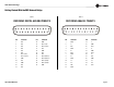
DBC Network Bridge Getting Started With the DBC Network Bridge Table 1 Table 2 DBC DB25F DIGITAL AES/EBU PINOUTS DBC DB25F ANALOG PINOUTS 13 1 14 25 PIN 13 1 14 25 FUNCTION PIN FUNCTION FUNCTION PIN FUNCTION 1 N/C 14 GND 1 GND 14 L– 2 N/C 15 AES1 (L/R)– 2 L+ 15 GND 3 N/C 16 AES3 (Ls/Rs)– 3 BSL– 16 BSL+ 4 N/C 17 N/C 4 GND 17 C– 5 N/C 18 GND 5 C+ 18 GND 6 N/C 19 N/C 6 BSR– 19 BSR+ 7 AES1 (L/R)+ 20 N/C 7 GND 20 R– 8 AES3 (Ls/Rs)+ 21 A
DBC Network Bridge Getting Started With the DBC Network Bridge 1.2 Communicating with the DBC Network Bridge: TCP/IQ™ Networking 1.2.1 The Network Wizard If you are setting up a dedicated audio network that is not part of another network, you can use the Network Wizard to set up your network easily. 1. Open IQwic. 2. Select Setup > Network Wizard. 3. Follow the instructions on the screen. 4. When done, skip to Step 4 on page 11. 1.2.
DBC Network Bridge Getting Started With the DBC Network Bridge 1.2.4 TCP/IQ Setup This example is based on a stand-alone system using switches and routers. The screen captures were done in Windows 2000; your exact configuration may vary. If your computer uses a network for other applications, please check with your Information Technology Department before making any changes. Section 1.2.5 includes a helpful worksheet for assigning addresses. 1. Turn on your computer and the rest of the system equipment.
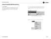
DBC Network Bridge Getting Started With the DBC Network Bridge 1B. Once the Properties window opens (Figure 1.5), click on Internet Protocol (TCP/IP). 1C. We recommend that you uncheck “Obtain an IP address automatically”, and check “Use the following address.” If you decide to set an IP address manually, specify an IP address. The IP address is four numbers between 1 and 255 separated by periods. For example, 126.126.0.1. Select a subnet mask.
DBC Network Bridge Getting Started With the DBC Network Bridge Table 3 1.2.5 TCP/IQ Addressing Worksheet Table 3 is an example of valid TCP/IP addresses on a stand-alone network. If the TCP/IQ network is going to be shared with other people, check with the Network Administrator for their addressing scheme. Without getting into all of the networking rules, the table lists approximately 20 network addresses out of a possible 65,534 addresses on this network.
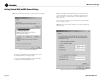
DBC Network Bridge Getting Started With the DBC Network Bridge 2. Select IQ Systems > IQwic > TCPIQ Utility (Figure 1.7). This launches the TCPIQ Utility on the master computer. 2B. Once TCP/IQ Utility has launched, select a single component and click on Set Address. In the Set Address window (Figure 1.9), set up a TCP/IQ address—it must be unique. Then set up the same Subnet mask for all of the components as well as the master computer. Set the IQ address, and select Send Code. 2C. Close the software.
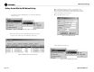
DBC Network Bridge Getting Started With the DBC Network Bridge 4. The Component Discovery screen appears and displays the message, “Searching for TCP/IQ components” (Figure 1.11). 5. The IQwic toolbar and Workspace appear. An icon of the DBC Network Bridge appears in the Workspace (Figure 1.12) Figure 1.12 The IQwic Toolbar (Top) and Workspace (Bottom) 6. Double-click the DBC Network Bridge Icon. The Input-Output window appears (Figure 1.13). Figure 1.13 The Input-Output Window Figure 1.
DBC Network Bridge Getting Started With the DBC Network Bridge 8. The processing functions appear. Click on the Unit Presets tab at the top. The Unit Presets window appears (Figure 1.14). 9. At the bottom right, select Preset 32, Standard Cinema. Then select Recall this Preset. Your system is running and ready to configure. Please continue reading the manual. If there are problems, please re-read Section 1.2.3 on addressing rules. Also read Chapter 6, Troubleshooting. Figure 1.
DBC Network Bridge Table of Contents Important Safety Instructions ........................................................... 2 3.3.5 Unbalanced Monitor Output Wiring ............................. 19 4.7.12 Scenes........................................................................39 Declaration of Conformity................................................................. 3 3.3.6 CobraNet Connections................................................. 19 4.7.13 Scene Editor .........................
DBC Network Bridge 2 Welcome At the heart of a Digital B Chain system, the Crown® DBC Network Bridge allows you to distribute multiple channels of digital audio over standard fast Ethernet hardware and cabling for use in traditional, e-cinema and dcinema applications.
DBC Network Bridge $"# .%47/2+ !%3 $)')4!, !5$)/ !.!,/' !5$)/ %4(%2.%4 30%!+%2 ,).% Fa u lt Fa u lt T h emr a l Fa u lt T h emr a l C lip -1 0 T h emr a l C lip -1 0 Powe r -2 0 B ird g e S ig n a l D a ta R eady 2 #4S W )1 0)0 530 #. Powe r -2 0 B ird g e S ig n a l D a ta C lip -1 0 Powe r -2 0 B ird g e S ig n a l R eady 1 ! D a ta R eady 1 2 1 #4S W )1 0)0 530 #. 2 #4S W )1 0)0 530 #.
DBC Network Bridge 3 Setup 3.1 Unpack and Install Your DBC Network Bridge Please unpack and inspect your product for any damage that may have occurred during transit. If damage is found, notify the transportation company immediately. Only you can initiate a claim for shipping damage. Crown will be happy to help as needed. Save the shipping carton as evidence of damage for the shipper’s inspection.
DBC Network Bridge 3 Setup 3.3 Wiring Chapter 1 describes how to make connections to the DBC Network Bridge. The information below describes the connections in detail. 3.3.1 Analog, Digital and Auxiliary Inputs Analog Line Input: DB25 female connector accepts eight balanced analog line-level analog inputs. Pinout matches Dolby CP-650 analog output. See Table 2 on page 5. Figure 3.
DBC Network Bridge 3 Setup 3.3.2 Balanced Input Wiring Balanced sources should be wired as shown below. Notice that the shield is not connected to the chassis ground of the source if the source is also connected to the AC ground (that is, it has a grounded AC plug). This prevents unwanted ground loops. 3.3.3 Unbalanced Input Wiring Unbalanced sources should be wired as shown below. The examples are grouped according to whether you use twin-lead shielded wire or single-lead coax (or twisted pair).
DBC Network Bridge 3 Setup 3.3.5 Unbalanced Monitor Output Wiring 3.3.6 CobraNet Connections The CobraNet network carries up to 32 channels of audio bidirectionally via a single cable. Connect the DBC Network Bridge to the CobraNet network using RJ45-terminated standard CAT 5 cable from the PRIMARY connector on the rear of the unit. The PRIMARY connection can either be connected to another DBC Network Bridge unit or other CobraNet-compatible component’s PRIMARY port.
DBC Network Bridge 4 Operation 4.1 Front Panel Controls and Indicators A. LCD Display LCD digital display shows information about the currently selected IQ address, inputs, presets, scenes, and firmware information. B. Input Display An eight-segment LED display matrix shows input signal presence for all eight analog or digital inputs. C. Power Indicator Blue LED shows that the unit is plugged in and AC power is being supplied. The unit does not have a power on/off switch. D.
DBC Network Bridge 4 Operation 4.2 Back Panel Controls and Connectors J. IEC AC Power Inlet Accepts an IEC AC power cord. The DBC Network Bridge has a universal power supply, and may be operated on AC line voltages from 100 VAC to 240 VAC at 50 Hz or 60 Hz. K. Multifunction Control Port One DB37M for analog inputs, digital inputs, +5VDC, +10VDC and ground. 8 input-switch closures, 8 analog 0-10VDC inputs, 16 output contact closures, +10VDC power source (1A), GND (1A+). L.
DBC Network Bridge 4 Operation 4.3 Navigating the LCD Control Screen 4.3.1 Functions, Controls and Screens The LCD Control Screen and its controls let you view and set up various parameters in the DBC Network Bridge. Settings made on the LCD screen are duplicated in IQwic software, and vice-versa. (DSP parameters cannot be adjusted with the LCD Control Screen. That is done in IQwic.) Getting around in the Menu is intuitive.
DBC Network Bridge 4 Operation 4.3.2 Operation Examples Operation Example 1 How to select Preset 5 using the LCD Control Screen: 1. After power-up, the Preset Screen appears. 2. Press Next until you see Preset 5. 3. Within 2 seconds, press Menu/Select. Operation Example 2 How to select the Digital/Surround Input using the LCD Control Screen: 1. After power-up, press and hold Menu/Select until the Input Board Menu appears. 2. Press Next until the arrow is by Digital/Surround. 3.
DBC Network Bridge 4 Operation 4.4 IQwic Overview This section describes how to set up the DBC Network Bridge from within IQwic software. It includes an overview of the various processing functions and associated windows. Presets or Scenes can be primed to change at set times or dates using the ‘Unit Event’ scheduler giving a reasonable degree of flexibility not unlike other show controllers. A Preset segue function enables Presets to be crossfaded in level for smooth transitions between setups.
DBC Network Bridge 4 Operation 4.5 Metering After you have followed the steps in Chapter 1, IQwic is running, and the Input/Output meters window (Figure 4.5) is at the left of the screen. Its features are described below. 1. Output Level Meters Audio level meters are provided for each output channel: Left, Right, Center, Subwoofer, Surround Left, Surround Right, Back Left, and Back Right. The meters sense the audio signal immediately after the audio output processing block.
DBC Network Bridge 4 Operation 4.6 General Tab Click on the Expand/Shrink Bar so that the Setup and Processing Functions appear. Click on the General tab at the top to view the General window (Figure 4.6). Its features are described below. 1 1. Real Time Clock The onboard Real Time Clock tracks day, date, hour, minute and second, and may be set to any date and time desired, or to match that of the computer running IQwic software.
DBC Network Bridge 4 Operation 4.7 Basic Processing Functions This section covers the basic processing functions found in the DBC Network Bridge configuration section of IQwic. 4.7.1 Signal Path Tab, Cinema Surround Form Click on the Signal Path tab and the Cinema Surround button at the top to view the Signal Path window (Figure 4.7). Its features are described below. 1 1. Cinema Surround / Advanced Buttons Selecting Cinema Surround will access the most common processing for Cinema Surround systems.
DBC Network Bridge 4 Operation 4.7.2 Input Compressor To open the Input Compressor window (Figure 4.8), select its icon (shown above) in any channel in the Signal Path window. The input compressor provides a means for controlling the dynamic range of input signals. It is a feed-forward type, which performs the compression after the Input Level Meter. The Input Compressor’s effect on input gain is metered by the Input Dynamic Cut/Boost Meter. 7 Seven parameters control this feature: 1.
DBC Network Bridge 4 Operation 4.7.3 Input Delay To open the Input Delay window (Figure 4.9), select its icon (shown above) in any channel in the Signal Path window. Signal Delay can be set for each output channel. This delay is especially useful in loudspeaker array alignment, where the crossovers, mix, and other processing is complete and the loudspeaker needs to be aligned to the system. Delay is displayed in milliseconds, feet, and meters.
DBC Network Bridge 4 Operation 4.7.4 EQ Filters To access the EQ Filters window (Figure 4.10), click on its icon (shown above) for any channel in the Signal Path window. 1. On/off Enables or disables filtering. 1 6 5 2. Add Button Click this to add a filter. A light green circle appears, indicating the active filter. 3. Frequency Response Graph Shows the frequency response of individual filters (not summed). After turning on filtering (1), click the graph to add a filter. A node appears.
DBC Network Bridge 4 Operation EQ Filters (continued) Please refer to Figure 4.11. 9. Frequency Select Field Another way to select the center frequency of an active filter is to enter its value here, either by typing or by pressing the arrow buttons. 10. Frequency Slider This is another way to set the center frequency of an active filter. 1 6 8 11. (Combined) Responses This graph shows the summed total of the filter networks for that input. 12.
DBC Network Bridge 4 Operation 4.7.5 All Outputs Volume Controls To open the volume controls for the output channels, click on the All Outputs icon in the Cinema Surround Signal Path window. See Figure 4.12. Here you can adjust the level, muting, and polarity of each channel. The master fader works like this: • After you set the individual channel levels, their relative positions will be maintained when you move the master fader. It acts like a group fader.
DBC Network Bridge 4 Operation 4.7.6 Signal Generator Click on the Signal Generator tab to open the Signal Generator window (Figure 4.13). This window provides a variety of test signals that can be applied to each output channel. Output levels and sine-wave frequency are adjustable. Figure 4.
DBC Network Bridge 4 Operation 4.7.7 CobraNet: Explanation In the Signal Path window, Cinema Surround form, is a DBC Network Channel Assign button which opens the CobraNet Output window (described on the next page). If you need to understand how CobraNet works, please read the following section. CobraNet is a technology developed by Peak Audio, Inc. that allows real time digital audio to be distributed over standard Fast (100Mb) Ethernet hardware.
DBC Network Bridge 4 Operation 4.7.8 CobraNet: Output In the Signal Path window, click on the DBC Network Channel Assign button to open the CobraNet Output window (Figure 4.14). The DBC Network Bridge’s eight CobraNet Outputs can be assigned to be transmitted on Slots in one of four CobraNet Bundles. The CobraNet Outputs can accept audio from either the corresponding ‘B’ Input Processing Section or the corresponding AUX Output Processing Section.
DBC Network Bridge 4.7.9 Booth Monitor Source Select In the Signal Path window, click on the Booth Monitor Source Select button to open the Booth Monitor Source Select window (Figure 4.15). 6 The controls in this window allow you to adjust the level, muting and polarity of selected output channels that feed your booth monitor speakers. You can also select CobraNet Bundles and Channels. 1. Input Selector Buttons 2 5 2. Level Slider This slider adjusts the level of the selected channel. 3.
DBC Network Bridge 4 Operation 4.7.10 Presets Click on the Unit Presets tab to open the Presets window (Figure 4.16). The DBC Network Bridge has the ability to reconfigure itself with a single command. Thirty-two 'Presets' can be stored and recalled via a variety of means including the front panel, a Control Port Input, or a scheduled 'Event'. Preset 32 is the standard cinema setup, which works in most cases. Preset 32 is explained under number 6 below. 3 1 2 1.
DBC Network Bridge 4 Operation 4.7.11 Preset Editor To open the Preset Editor window (Figure 4.17), start In the Unit Presets window, right-click on a preset number, and select Edit Presets. Note: Preset 32, Standard Cinema, cannot be edited. 1 1. Preset Name The name of the currently selected Preset is displayed here. You can give it a new name if desired. 2 2. Show This area of the Preset Editor lets you select which control types you want to view in the Preset Control Window (3). 4 3.
DBC Network Bridge 4 Operation 4.7.12 Scenes Click on the Unit Scenes tab to open the Scenes window (Figure 4.18). Remember that an object is a software processor in the DBC Bridge. There are times when only a few objects’ settings need to be changed and this is the function of 'Scenes'. DBC Network Bridge Scenes allow up to 50 objects to be grouped together and changed to a specific state with a single command.
DBC Network Bridge 4 Operation 4.7.13 Scene Editor To open the Scene Editor window (Figure 4.19), click on the Edit button for any channel in the Scene window. 1. Scene Select the Scene to be edited in the ‘Scene’ box at top, or click on one of the 32 buttons located at the right of the screen. 2 3 1 5 2. Controls The ‘Controls’ buttons let you view your choice of all parameters, dB parameters or Logical parameters. 3.
DBC Network Bridge 4 Operation 4.7.14 Events Scheduler Click on the Unit Events tab to open the Events Scheduler window (Figure 4.20). Different configurations can be triggered at particular times. The DBC Network Bridge has an internal real time clock that can be used to set up a schedule for recalling Presets or Scenes. By using the 'Event Scheduler' to recall unit settings at certain times, the unit can be used in a variety of different ways.
DBC Network Bridge 4 Operation One Time Events In the Events Scheduler window, click on the Edit button to the right of any Event number. The One-Time Event window will open (Figure 4.21). Figure 4.21 One-Time Event Window An Event can be scheduled to occur only once, and the time of the Event can be programmed by choosing 'once'. The exact time of the Event can then be set. Periodic Events In the One-Time Event window, click on the Periodically button to open the Periodic Event window (Figure 4.22).
DBC Network Bridge 4 Operation 4.8 General Firmware Features Note: The following features are accessed via IQwic software unless otherwise stated. Refer to Figure 4.24, DBC Network Bridge Signal Flow Block Diagram for feature locations in the audio signal chain. 4.8.1 Input Level Meters Audio level peak program meters are provided for each input. The meters sense the audio signal immediately after analog to digital conversion, and respond with 1.7 millisecond attack and 350 millisecond release.
DBC Network Bridge 5 Advanced Operation 5.1 Advanced Operation Table of Contents 5 Advanced Operation ........................................... 44 5.3.3 Input Gate.....................................................................57 5.1 Advanced Operation Table of Contents ................................. 44 5.3.4 Auto Leveler .................................................................58 5.2 Advanced Processing Functions........................................... 45 5.3.5 Automixer........
DBC Network Bridge 5 Advanced Operation 5.2 Advanced Functions 5.2.1 CobraNet: Setup To open the CobraNet Setup window, click on the CobraNet tab, then click on the CobraNet Setup tab. The CobraNet Setup window opens (Figure 5.1). The CobraNet Setup tab allows overall control of the DBC Network Bridge’s CobraNet functions. Several labels and information are available: 1. System Name This user-defined label indicates the name of the particular DBC Network Bridge. 2.
DBC Network Bridge 5 Advanced Operation CobraNet: Setup (continued) Please refer to Figure 5.2. 7. IP Address The Internet Protocol address that is assigned by the system integrator. Used as a standard part of Ethernet networking transmission protocols and works much like a zip/postal code for the unit on the network. 8. Conductor The CobraNet 'Setup' tab indicates information about the status of the Conductor (the CobraNet timing-master device).
DBC Network Bridge 5 Advanced Operation 5.2.2 CobraNet: Input To access the CobraNet Input window, click on the CobraNet tab, then click on the CobraNet Input tab. The CobraNet Input window will open (Figure 5.3). The DBC Network Bridge can accept three Bundles from the CobraNet network and route the audio Slots of those Bundles into the processing and mixing of the unit. These three Bundles (RxB, RxC, and RxD), are assigned Bundle numbers by the Bundle window.
DBC Network Bridge 5 Advanced Operation 5.2.4 Control Port The Control Port provides a means for external monitoring and control of ‘objects’ (software processors) within the DBC Network Bridge. It can be used to turn peripherals on and off, send signals to other system components, receive digital and/or analog signals from other components, and indicate status of the input gates. 1 2 The Control Port implements sixteen outputs and sixteen inputs along with power supply outputs and common grounds.
DBC Network Bridge 5 Advanced Operation Control Port Window: Digital Inputs Figure 5.6 Sample Control-Port Digital Input Circuit The Digital Inputs are high or low only. They are current driven and will accept +5V or +10V inputs (+25VDC max), and are well suited for sensing contact closure (Figure 5.6). They switch at approximately +1 VDC. They can be used to control one or more objects with the DBC Network Bridge.
DBC Network Bridge 5 Advanced Operation Control Port Assignment Dialog (continued) Please refer to Figure 5.8. 5. Add / Remove Buttons Once the desired object has been found in the Controls List (4), highlight it and press the Add button (5). The object will appear in the Object List (6) at the bottom of the window. Highlight a particular object in the bottom window to edit its attributes. You can remove a highlighted object by pressing the Remove button. 1 2 7 3 8 4 9 10 11 12 6.
DBC Network Bridge 5 Advanced Operation Control Port: Condition Logic Setup Window To open the Condition Logic Setup window (Figure 5.9), press the Edit Mapped Conditions button in the Control Port window. 1 2 1. Condition Allows up to 64 different binary combinations of pin states. Up to eight inputs are allowed in any state, giving up to 255 different combinations for each of the the 64 configurations. 2. Name Naming convenience for the configuration. 64 names are available. 3.
DBC Network Bridge 5 Advanced Operation Control Port Window: Digital Outputs Section In the Control Port window, find the Digital Outputs section (Figure 5.10). There are eight digital outputs. Each output may be controlled manually, configured to indicate the state of a binary object or, configured to indicate whether a particular Preset is loaded. There is one indicator and five controls for each output: Figure 5.10 Digital Outputs Section of the Control Port Window 1.
DBC Network Bridge 5 Advanced Operation Control Port Window: Analog Inputs Section (AIN 1-8) Find the Analog Inputs section (Figure 5.13) in the Control Port window. It has a status indicator and level meter for each input channel. The Control Port analog inputs allow a 0 to +10 VDC signal to be input to allow remote control of continuously variable objects such as faders or filter frequencies. They can also be used to control switched objects (just like the Digital Inputs).
DBC Network Bridge 5 Advanced Operation 5.3 Advanced Form Firmware Features This section explains the advanced signal-path features in the DBC Network Bridge. From the Signal Path tab, click on the Advanced button at the top. This opens the Advanced Form window (Figure 5.16). Its functions are listed below, and each function is explained in the following pages. 21 1 22 2 3 4 5 6 23 24 7 8 9 10 25 11 12 13 14 15 16 17 Note that most functions are duplicated on all the input and output channels.
DBC Network Bridge 5 Advanced Operation 5.3.1 Input Path Starting from the Signal Path window, you can access the Input Path window (Figure 5.17) for any channel by clicking on either an input-select button or the Input Path icon (shown above) for the channel. 1. Input Selector Choose which input channel to view by either pressing the blue or green input channel required or, pick an input from the drop-down box. 1 2 2. Input Meter The switched input signal is sampled and displayed. 3.
DBC Network Bridge 5 Advanced Operation 5.3.2 Input Delay Starting from the Input Path window, you can access the Input Delay window (Figure 5.19) by clicking on its icon (shown above). A delay can be added to any of the Input Processing Sections in order to timeequalize the various input signals. Delay is displayed in IQwic software in time, feet, and meters. Control range is from 0 to 100 milliseconds in 20 microsecond steps. Delay time can be adjusted up to a maximum of 2 seconds for each channel.
DBC Network Bridge 5 Advanced Operation 5.3.3 Input Gate Starting from the Input Path window, you can access the Input Gate window (Figure 5.20) by clicking on its icon (shown above). The Input Gate feature allows signals above a certain level to pass and attenuates lower level signals. When 'open', the Input Gate passes the input signal un-attenuated. When 'closed', it attenuates the input signal by an amount specified with the Depth control.
DBC Network Bridge 5 Advanced Operation 5.3.4 Auto-Leveler Starting from the Input Path window, you can open the Auto-Leveler window (Figure 5.22) by clicking on its icon (shown above). The Auto-leveler works in tandem with the Input Gate to compensate for long-term average input levels that vary over time. When the Auto-leveler is enabled, the open state gain of the corresponding Input Gate, normally 0 dB, is adjusted dynamically to achieve a desired average output level.
DBC Network Bridge 5 Advanced Operation 5.3.5 Automixer Automatic mixers allow 'hands-free' mixing that minimizes many of the undesirable effects of using multiple microphones. Applications such as conference rooms, training rooms and boardrooms typically implement many microphones for individual speakers. Simultaneously mixing all microphones with acceptable gain before feedback manually is not possible.
DBC Network Bridge 5 Advanced Operation Automix Controls Starting in the Input Path window, you can open the Automix Controls window (Figure 5.23) by clicking on its icon (shown above). 8 There are four individual Input controls: 1. Priority Assigns a relative priority to each channel. Control range is 1 to 8, where 1 is the highest priority and 8 is the lowest priority. 7 2. Depth of Cut Sets the ‘ducked’ mic gain. Control range is from -100 to 0 in 0.5dB steps. 3.
DBC Network Bridge 5 Advanced Operation Automix Matrix Access the Automix Matrix (Figure 5.24) by pressing the Automix Matrix button in the Signal Path window. This window is an interactive overview of all the possible automix routings assignments and priorities. There are three main automix functions; Ducking, NOM and Adaptive Gating and these work as a group.
DBC Network Bridge 5 Advanced Operation Automixing Group Controls 14 Access the Automixing Group Controls (Figure 5.25) by pressing the Auto-mix Groups button in the Signal Path window. 11 12 There are two group controls and two group indicators for this feature: 1. Priority Mix Enable Turns Ducking Priority Mix on and off for the automix group. 2 13 3 4 2. Max Number of Open Mics Sets the max number of open mics within the automix group.
DBC Network Bridge 5 Advanced Operation Automixing Group Controls (continued) 14 Please refer to Figure 5.26. Adaptive Gating Adaptive Gating dynamically modifies the Input Gate thresholds in the auto-mix group as a function of the ambient level in the room. The ambient level is computed as the weighted average of the closed mic input levels. The weighted average makes it possible to compensate for mic locations with different ambient levels.
DBC Network Bridge 5 Advanced Operation 5.3.6 Solo/Mute At the top of the Signal Path window, find the Solo/Mute button. Pressing this button opens the Solo/Mute window (Figure 5.27). It lets you monitor the status of the Input and Output channel mutes and solos. From here, individual channels can be soloed for preview purposes, and can be muted equally. All solos and mutes can be switched in or out for the Inputs and Outputs separately. Figure 5.
DBC Network Bridge 5 Advanced Operation 5.3.7 Output Path Starting in the Signal Path window, at the end of the Output processing section, you can access the Output Path window (Figure 5.28) by clicking on its icon (shown above). In addition to the output of each of the sixteen Input Processing Sections, the eight CobraNet Inputs are fed to the Matrix Mixer, providing a 24 Input by 10 Output fully independent crosspoint mix as controlled by the Input/Output Matrix.
DBC Network Bridge 5 Advanced Operation 5.3.8 Ambient Leveler Starting in the Output Path window, you can access the Ambient Leveler window (Figure 5.30) by clicking on its icon (shown above). The Ambient Leveler expands the output channel gain to compensate for a sensed ambient level. The ambient level can be sensed from any of the sixteen Input Processing Sections, or the computed ambient level from one of the 32 auto-mix groups.
DBC Network Bridge 5 Advanced Operation 5.3.9 Output Limiter Starting in the Output Path window, you can open the Output Limiter window (Figure 5.31) by clicking on its icon (shown above). This function lets you monitor and control the peak output level. It is especially valuable for the protection of amplifiers, loudspeakers and other audio equipment. The Output Limiter operates like a compressor with an infinite compression ratio, preventing the output level from exceeding the specified Threshold.
DBC Network Bridge 5.3.10 Outputs Button Locate the Outputs button at the top-right of the Advanced Form Signal-Path window. Press this button to view all the output channels’ processing (Figure 5.32). Figure 5.
DBC Network Bridge 5.4 Technical Description Following is a technical description of the operation of the DBC Network Bridge. Please refer to the System Block Diagram (Figure 4.24). Audio Input Section Each audio input signal first passes through a balanced filter designed to eliminate RF interference. The RF filters are a balanced network of chokes, ferrite beads, and capacitors that attenuate both common-mode and differential-mode signals above 500 kHz.
DBC Network Bridge 6 Troubleshooting CONDITION: Power indicator is off. POWER AES/EBU DATA POSSIBLE REASON CONDITION: Input LEDs are off. INPUT 1 AES/EBU DATA 5 POSSIBLE REASON: 6 7 8 6 7 8 • The source feeding the DBC Network Bridge is not producing a signal. Check its output signal. CONDITION: AES/EBU indicator is off, even though the unit is being fed an AES/EBU signal. • The cable between the signal source and the DBC Network Bridge is defective. Replace or repair it.
DBC Network Bridge 6 Troubleshooting IN USE/ COND LINK/ ACT CONDITION: IN USE/CONDUCTOR LED does not light, even though the network cable is plugged in. CONDITION: Both LEDs flashing. POSSIBLE REASON: • • • Ethernet link is broken. Network connection is 10 Megabits instead of 100 Megabits. CONDITION: LINK/ACTIVITY LED does not light, even though the network cable is plugged in. POSSIBLE REASON: IN USE/ COND Fatal error.
DBC Network Bridge 6 Troubleshooting If the DBC Network Bridge seems to be functioning in unexpected ways, go to the Signal Path tab and select Advanced. If the unit is set up for Preset 32, Standard Cinema Setup, only four icons in each channel should be lit. These icons are input level, input delay, input path filter, and output level (as in Figure 6-1). If other icons are lit as in the example Figure 6-2, the unit is no longer functioning as a cinema bridge, but as a mixer.
DBC Network Bridge 7 Specifications Audio Dynamic Range > 108 dB (A-weighted, 20 Hz-20 kHz) Digital Sampling 24-bit, 48 kHz Frequency Response ± 0.5 dB, 20 Hz-20 kHz Total Harmonic Distortion < 0.
DBC Network Bridge 7 Specifications Power Required AC Mains Universal AC input. Operates from 100 VAC to 240 VAC at 50/60 Hz, 24W nominal. AC Line Connector 15A IEC AC power inlet Mechanical Cooling Convection cooled, no vents, no fans Dimensions 19 in. (48.3 cm) W x 1.75 in. (4.4 cm) H x 16 in. (40.6 cm) D Net Weight 15.3 lbs (6.
DBC Network Bridge 8 Appendix A: TCP-IQ Network Basics 8.1 Glossary The following glossary explains network terminology. It is arranged in logical order rather than alphabetical order. Example: Suppose the IP ADDRESS of a device is 126.126.17.42 and the SUBNET MASK is 255.255.0.0. Network: A group of interconnected components, such as a central computer, network switching equipment, and other computers or devices. That means, (126.126) is the NETWORK ID. The remaining set of numbers (17.
DBC Network Bridge 8.2 TCP/IQ Network Basics TCP/IQ Tis a network based protocol that has the ability to control and monitor IQ components over a common TCP/IP network. For IQ components that have CobraNet capability, TCP/IQ has the ability to control and monitor these IQ components over the same Ethernet network used for CobraNet audio, resulting in a single Category-5 connection for control, monitoring, and digital audio. Figure 8.1 shows a typical TCP/IQ network.
DBC Network Bridge Communications between networks is allowed, but requires the use of a special piece of equipment called an IP Router. The router acts as a Gateway to allow this communication to exist. Any data traffic that is to go to the other network is routed through the IP Router. The CobraNet data is held behind but IP data goes through.
DBC Network Bridge The MAC address does uniquely identify each TCP/IQ component and can be used to establish the physical location of the unit. The binding of the MAC address to the IQ address through the use of the TCP/IQ Utility assures that each TCP/IQ component is physically in the right position. The use of the IP address establishes the Local Area Network (LAN) and what components reside within that LAN.
DBC Network Bridge Today, commonly available networking cards are 10/100Base-T capable, which allows them to be used on either 10BaseT or 100Base-T networks. Fast Ethernet distance limitations apply to CobraNet installations: 100 meters over Cat-5 copper cable, 2 kilometers over multimode fiber. Proprietary Fast Ethernet via single mode fiber solutions can reach even further. 8.3.2 Audio Specs CobraNet implements fixed sample rates of 48 kHz or 96 kHz.
DBC Network Bridge 9 Service Crown amplifiers are quality units that rarely require servicing. Before returning your unit for service, please contact Crown Technical Support to verify the need for servicing. This unit has very sophisticated circuitry which should only be serviced by a fully trained technician. This is one reason why each unit bears the following label: CAUTION: To prevent electric shock, do not remove covers. No user serviceable parts inside. Refer servicing to a qualified technician.
DBC Network Bridge 10 Warranty UNITED STATES & CANADA SUMMARY OF WARRANTY Crown International, 1718 West Mishawaka Road, Elkhart, Indiana 46517-4095 U.S.A. warrants to you, the ORIGINAL PURCHASER and ANY SUBSEQUENT OWNER of each NEW Crown product, for a period of three (3) years from the date of purchase by the original purchaser (the “warranty period”) that the new Crown product is free of defects in materials and workmanship.
DBC Network Bridge 11 Warranty (continued) WORLDWIDE EXCEPT USA & CANADA SUMMARY OF WARRANTY WHAT THE WARRANTOR WILL DO Crown International, 1718 West Mishawaka Road, Elkhart, Indiana 46517-4095 U.S.A.
DBC Network Bridge Crown Audio Factory Service Information Shipping Address: Crown Audio Factory Service, 1718 W. Mishawaka Rd., Elkhart, IN 46517 PLEASE PRINT CLEARLY SRA #: __________________(If sending product to Crown factory service.
DBC Network Bridge page 84 Operation Manual