
Network Hardware User Manual


Operation Manual
DBC Network Bridge
page 4
1 Getting Started With the DBC Network Bridge
Welcome! This Quick-start guide will get you up and running
in a short time. Then please refer to the rest of the manual for
details on the DBC™ Network Bridge and its operation.
IMPORTANT: Unplug power cord from AC outlet
before wiring.
1.1 Hardware Installation
You will need:
• Crown power amplifiers with USP3-CN PIP modules
installed, or Crown I-Tech CobraNet- version power
amplifiers
• A computer running IQwic software
• A 100Mb network switch
• An Ethernet cable (RJ45 connector on each end) for
use between the computer and network switch
• Two Ethernet cables for use between the DBC Network
Bridge and the network switch. One cable is sufficient,
but two allow redundancy.
• An Ethernet cable between the network switch and
each USP3-CN module (or Ethernet connector)
installed in a Crown power amplifier.
1.1.1 Audio and Network Connections
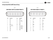
Please refer to Figures 1.1 and 1.2.
1. Mount the DBC Network Bridge in a standard 19-inch
(48.3-cm) equipment rack or cabinet.
2. Turn off all equipment that will connect to the unit.
3. Connect the AES/EBU digital output signal from your cin-
ema processor, media player, or feature server to the analog
DB25 connector on the back of the DBC Bridge. DB25 wiring
is shown in Table 1 on the next page. Alternatively, connect
the analog output signal from your cinema processor to the
Analog DB25 connector on the back of the DBC Bridge.
DB25 wiring is shown in Table 2 on the next page.
4. See Figure 1.2. Connect any auxiliary mic or line signals
to the female XLR Auxiliary Inputs on the back of the DBC
Network Bridge. Set the MLP switch for Mic, Line, or Phan-
tom-powered mic. Adjust gain potentiometers to optimize
gain structure.
Figure 1.1 System Wiring
!
! !
! !
$"#.%47/2+
!%3$)')4!,!5$)/
!.!,/'!5$)/
%4(%2.%4
30%!+%2,).%
1
1
Powe r
2 3 4 5 6 7 8 9 10 1112
234
9101112
5678
13 14 15 16
NETGEAR
$"##ONTROL0#
#4SW)10)0530#.
#4SW)10)0530#.
#4SW)10)0530#.#4SW)10)0530#.#4SW)10)0530#.
%THERNET3WITCH
%THERNET3WITCH
$"#"RIDGE
$"#)NPUT/PTIONS
$OLBY#0 DTS8$
DTS8$0
!%3!%3
!NALOG
!NALOG
!NALOG
3URROUND#HANNELS
3CREEN#HANNELSAND3UBWOOFERS
Power
Data
Bridge
Fault
Thermal
-20
Signal
12
Ready
Clip
-10
Power
Data
Bridge
Fault
Thermal
-20
Signal
12
Ready
Clip
-10
Power
Data
Bridge
Fault
Thermal
-20
Signal
12
Ready
Clip
-10
Power
Data
Bridge
Fault
Thermal
-20
Signal
12
Ready
Clip
-10
Power
Data
Bridge
Fault
Thermal
-20
Signal
12
Ready
Clip
-10
1
1
Powe r
2 3 4 5 6 7 8 9 10 1112
234
9101112
5678
13 14 15 16
NETGEAR
Power
Data
Bridge
Fault
Thermal
-20
Signal
12
Ready
Clip
-10
Power
Data
Bridge
Fault
Thermal
-20
Signal
12
Ready
Clip
-10
Power
Data
Bridge
Fault
Thermal
-20
Signal
12
Ready
Clip
-10
Figure 1.2 Audio Inputs on the Back Panel of the DBC Bridge
XLR connector wiring:
pin 1: shield
pin 2: signal hot
pin 3: signal cold