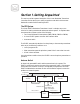
® RTC Operator Restart Tx1RF Power Threshold Tx2RF Power Threshold VOX Attack Timeout Redundant Transmitter Controller VOX Decay Timeout Tx1AudioOn HeartBeat Tx2AudioOn AntennaPos1 Tx1Fault AntennaPos2 Tx2Fault Shutdown FM RTC Redundant Transmitter Controller User's Manual ©2001 Crown Broadcast, a division of International Radio and Electronics, Inc. 25166 Leer Drive, Elkhart, Indiana, 46514-5425 U.S.A.
Revision control Revision Print date Revision 3 September 2002 Important Notices ©2001, Crown Broadcast, a division of International Radio and Electronics, Inc. All rights reserved. No part of this publication may be reproduced, transmitted, transcribed, stored in a retrieval system, or translated into any language in any form by any means without the written permission of Crown International, Inc. Printed in U.S.A. Crown attempts to provide information that is accurate, complete, and useful.
Contents Section 1-Getting Acquainted ........................................... 1 The RTC System ............................................................................................................ 1 Antenna Switch ............................................................................................................. 1 Transmitters................................................................................................................... 2 RF Load (optional) ..........................
Notes iv
Section 1-Getting Acquainted This section provides a general description of the Crown Redundant Transmitter Controller and introduces you to safety conventions used within this document. Review this material before installing the RTC. The RTC System The Crown FM RTC Redundant Transmitter Control is a simple, easy to use solution for creating redundant broadcast transmitter systems.
Transmitters The Crown FM RTC interfaces directly with two Crown transmitters. All signals connect to the FM RTC through the transmitter Remote I/O connector on the back of the transmitter. • • • • Transmitter Composite Audio Output Meter RF Watts Output Carrier Enable Transmitter Fault Summary Safety Considerations Crown Broadcast assumes the responsibility for providing you a safe product and safety guidelines during its use.
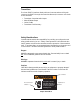
Operator Restart Tx1RF Power Threshold Tx2RF Power Threshold VOX Attack Timeout VOX Decay Timeout Tx1AudioOn HeartBeat Tx2AudioOn AntennaPos1 Tx1Fault AntennaPos2 Tx2Fault Shutdown Front Panel Indicators Eight front panel LED indicators display the status of the FM RTC system.
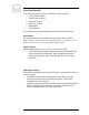
Operator Restart Tx1RF Power Threshold Tx2RF Power Threshold VOX Attack Timeout VOX Decay Timeout Tx1AudioOn HeartBeat Tx2AudioOn AntennaPos1 Tx1Fault AntennaPos2 Tx2Fault Shutdown Tx1 and Tx2 Faults The red Tx1 and Tx2 Fault indicators illuminate for the following conditions: • A fault in the indicated transmitter. The exact fault is indicated on the transmitter’s front panel.
Front Panel Controls There are six front panel controls on the FM RTC. These controls are: • • • • • • Tx1 RF Power Threshold Tx2 RF Power Threshold VOX Attack Timeout VOX Decay Timeout System Reset Operator Restart The following sections detail the operation and use of each of these controls. System Reset The System Reset is the only unlabeled control on the FM RTC front panel.
Transmitter Power Threshold The power threshold controls set the low power switching points on the FM RTC. The adjustments ranges from 5 to 500 watts. • Tx1 RF Power sets the RF low power point where the FM RTC switches from the primary to the secondary transmitter. The rf power must drop below the threshold for longer than 4 seconds before the FM RTC switches to the secondary transmitter.
Section 2—Installation This section provides important guidelines for installing your FM RTC. Review this information carefully for proper installation. Unpacking The Crown FM RTC is packed with the following items. • • • • FM RTC Two RF cables Two 15-pin interface cables Antenna relay with attached cable Save the box and packaging material that the FM RTC was packed in should you need to return it for factory service.
Section 3—Operation This section provides general operating parameters of your transmitter and a detailed description of its front panel display. Start up sequence This section describes the starting sequence for a Crown FM RTC system. Startup consists of two parts: • Presetting controls • Power up Presetting controls Before starting the FM RTC system, preset the following controls. • Transmitter Power Threshold-Set below the maximum operating power of each transmitter.
Section-4 Troubleshooting This section provides guidelines for troubleshooting common problems that may occur with a Crown FM RTC system. The following subsections list tests and suggest corrective actions for each identified problem. No heartbeat light, no operation, If the Heartbeat LED does not flash and the FM RTC fails to operate, verify power to the FM RTC. • Verify that AC power (90 to 264 Volts AC, 50-60 Hz) is present at the power cord.
No Audio Signal Detected The FM RTC Tx1 and Tx2 Audio On indicators illuminate when the FM RTC is detecting audio from the transmitters. Should the FM RTC indicate a loss of either audio source. • Verify that the transmitter has program audio connected to the audio input. • Verify that the transmitter output audio is connected to the FM RTC Remote I/O channel • Verify that the audio level is approximately 12 volts peak-to-peak. If these checks fail to correct the problem, return the FM RTC for repair.
Section 5—Service and Support We understand that you may need various levels of support or that the product could require servicing at some point in time. This section provides information for both of these scenarios. Service The product warranty (see opposite page) outlines our responsibility for defective products.
Three-Y ear Limited W arranty Three-Year Warranty North America Only SUMMARY OF WARRANTY We, Crown Broadcast, a business unit of International Radio and Electronics Company, Inc.
Factory Service Instructions To obtain factory service, complete the bottom half of this page, include it with the unit, and ship to: International Radio and Electronics Company, Inc. 25166 Leer Drive Elkhart, Indiana, U.S.A. 46514-5425 For units in warranty (within 3 years of purchase from any authorized Crown Dealer): We pay for ground UPS shipments from anywhere in the continental U.S. and Federal Express Second Day service from Hawaii and Alaska to the factory and back to you.