
User`s manual


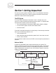


Table Of Contents
- Contents
- Section 1-Getting Acquainted
- The RTC System
- Antenna Switch
- Transmitters
- RF Load (optional)
- Safety Considerations
- Dangers
- Warnings
- Cautions
- Front Panel Indicators
- Heartbeat LED
- Tx1 and Tx2 Audio On
- Tx1 and Tx2 Faults
- Antenna Position 1 and 2
- Shutdown
- Front Panel Controls
- System Reset
- Operator Restart
- VOX Timeout Settings
- Transmitter Power Threshold
- Section 2-Installation
- Unpacking
- Operating location
- Power connections
- Mounting and connecting
- RF Connections
- Section 3-Operation
- Start up sequence
- Presetting controls
- Power up
- End of day operation
- Section-4 Troubleshooting
- No heartbeat light, no operation,
- No Audio Signal Detected
- Excessive or insufficient VOX time
- RF power settings
- Tx1 or Tx2 fault locked out
- Section 5-Service and Support
- Service
- 24-Hour Support
- Spare Parts
- Factory Service Instructions

1
Section 1-Getting Acquainted
This section provides a general description of the Crown Redundant Transmitter
Controller and introduces you to safety conventions used within this document.
Review this material before installing the RTC.
The RTC System
The Crown FM RTC Redundant Transmitter Control is a simple, easy to use
solution for creating redundant broadcast transmitter systems. A complete redun-
dant transmission system consists of the following:
• Two Crown Broadcast FM transmitters (FM30, FM100, FM250 or FM500)
• A Crown FM RTC system controller with interface cables
• An antenna switch
The FM RTC automatically switches from the primary to the secondary transmitter
when any of the following conditions occur
• Loss of program audio
• When transmitter power drops below a preset limit for more than 4 seconds
• A fault in the transmitter.
Once the problem condition clears, the FM RTC returns the primary transmitter to
operation.
Antenna Switch
An electrically operated RF switch switches transmitters in the system. The
FM RTC continuously monitors the state of the antenna RF switch. If the antenna
switch either fails to switch correctly or unexpectedly changes states, the Crown
FM RTC disables both transmitter carriers until the station engineer corrects the
problem and resets the system.
FM RTC
PrimaryFM
Transmitter
SecondaryFM
Transmitter
Antenna
Switch
Antenna
AC Power
Remote I/O Cable
RFSwitch Control
AuxI/O,RS-232
Relay Output, and 2
Opto-Isolated Inputs
Progam Audio
Remote I/O Cable
RF Coax Port 1 RF Coax Port 3
RF Coax Port 2