
Specifications


2–10
FM500 User's Manual
2.7 Audio Input Connections
Attach audio inputs to the Left and Right XLR connectors on the rear panel. (The
Left channel audio is used on Mono.) Pin 1 of the XLR connector goes to chassis
ground. Pins 2 and 3 represent a balanced differential input with an impedance of
about 50 kΩ. They may be connected to balanced or unbalanced left and right
program sources.
The audio input cables should be shielded pairs, whether the source is balanced or
unbalanced. For an unbalanced program source, one line (preferably the one
connecting to pin 3) should be grounded to the shield at the source. Audio will
then connect to the line going to pin 2.
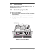
Illustration 2-10 XLR Audio Input Connectors
By bringing the audio return line back to the program source, the balanced
differential input of the transmitter is used to best advantage to minimize noise.
This practice is especially helpful if the program lines are fairly long but is a good
practice for any distance.
If the program source requires a 600 Ω termination, install resistors on the 8–pin
DIP socket on the motherboard (socket A501 located between the XLR
connectors). See the motherboard schematic, on page 6–13.
SCA IN
COMPOSITE IN
MONITOR
R
L
23
REMOTE I/O
RIGHT
LEFT/MONO
1
Audio
Inputs