
Specifications


2–13
Installation
2.13 Program Input Fault Time-out
You can enable an automatic turn-off of the carrier in the event of program failure.
To enable this option, see the table on the next page. The time between program
failure and carrier turn-off is set by a jumper (JP701) on the voltage regulator
board (see Illustration 6–4 for board location). Jumper pins 1 and 2 (the two pins
closest to the edge of the board) for a delay of approximately 30 seconds; pins 3 and
4 for a 2–minute delay; pins 5 and 6 for a 4–minute delay, and pins 7 and 8 for an
8–minute delay.
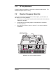
2.14 Remote I/O Connector
Remote control and remote metering of the transmitter is made possible through a
15–pin, D-sub connector on the rear panel. (No connections are required for
normal operation.)
Illustration 2–14 Remote I/O Connector
The following table summarizes the Remote I/O pin connections.
SCA IN
COMPOSITE IN
MONITOR
R
L
23
REMOTE I/O
RIGHT
LEFT/MONO
1
Remote I/O